


Chapter 1 Overview
1-2 Chapter 1 Overview
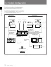
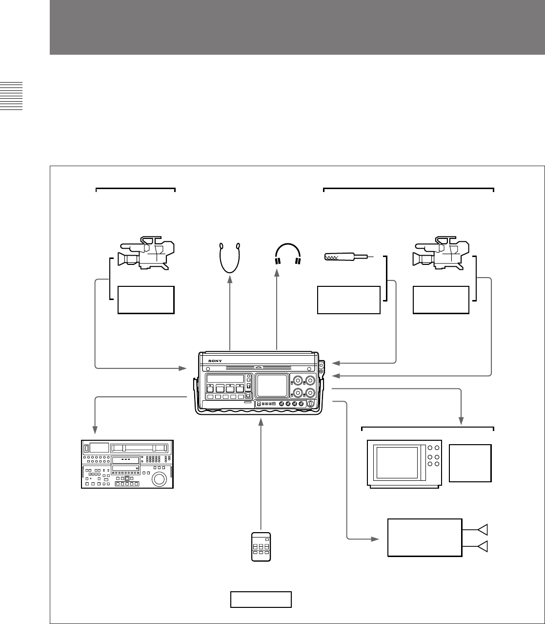
1-2 System Configuration
The following figure shows the configuration of a
typical system centered on the DVW-250/250P.
For details, such as the connector names, see Section 4-1-1
“Connecting Digital Equipment” (page 4-1) and Section 4-
1-2 “Connecting Analog Equipment” (page 4-2).
Typical DVW-250/250P system configuration
Digital equipment
Color video camera
Switching
Single video/audio input
channel
Single video/audio
output channel
VTR etc.
VTR etc.
Earphone Headphones
Analog equipment
Color video camera
Component signal
VTR etc.
Switching
Four audio input
channels (1 to 4)
Video monitor
VTR, FPU (Field
Pickup Unit), etc.
Four audio output
channels
Stereo amplifier Speakers
Control signal
channel
Microphone
BVR-3 Remote Controller
or
Composite signal
Single video/audio
input channel
Two video output
channels (composite)
DVW-250/250P
Editor etc.
Tape recorder,
etc.