


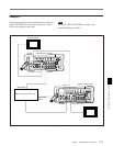

Chapter 6 Setup Operations
Chapter 6 Setup Operations 6-3
EXIT
EXIT
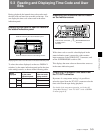
OFF: Picture will not shift by processing
the output video.
ON: Picture shifts if recorded color
framing is not continuous.
When the color framing
information in a recorded signal
is not continuous, select whether
or not to suppress the picture
shift.
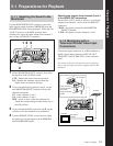
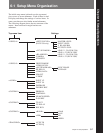
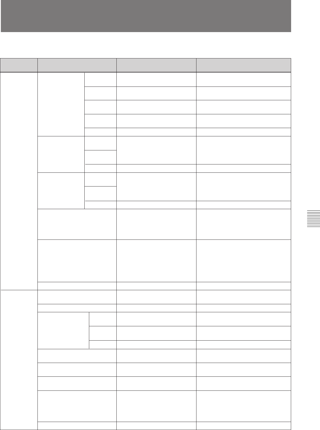
6-3 Setup Menu Settings
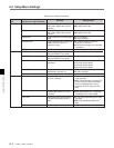
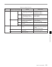
Setup menu settings
Top menu
item
Submenu items (nested
submenus in angle brackets)
<VIDEO 1>
Function Setting values
<SETUP LEVEL>
(DVW-250 only)
MASTER
LEVEL
Master level 0.0 % to 10.0 % in 0.5 % steps
INPUT
LEVEL
Setup level of input signal
Setup elimination in vertical
blanking interval
V BLANK
RM
OUTPUT
LEVEL
Setup level of output signal
0.0 % to 10.0 % in 0.5 % steps
MST: same value as master level
OFF: no setup elimination
ON: Carry out setup elimination
0.0 % to 10.0 % in 0.5 % steps
MST: same value as master level
<Y/C SEP MODE> LINE 12...20
(DVW-250)
Toggle Y/C separation for each
line.
BPF: Carry out Y/C separation.
B/W: no Y/C separation; treat as Y
signal.
EXIT Return to <VIDEO 1> menu.
EXIT Return to <VIDEO 1> menu. —
<BLANKING> LINE 12...20
(DVW-250)
THRU: no blanking
BLNK: blank input line
LINE 9...22
(DVW-250P)
Toggle blanking for each input
line
ON: output
OFF: no output
—
SC
PHASE
Select standard/nonstandard
composite input signal.
EXIT Return to <VIDEO 1> menu. —
CAMERA Select input signal from camera.
STD/NSTD
EXIT Return to top menu. —
<VIDEO 2>
Select freeze mode.FREEZE MODE FLD: Freeze single field.
FRM: Freeze frame.
Set the video output level. –3 dB to +3 dB in 0.1 dB steps
<SYSTEM PHASE>
0 to 965 in 0.29 nsec steps (DVW-250)
0 to 779 in 0.29 nsec steps (DVW-250P)
SYNC
PHASE
Adjust the phase of the sync
signal.
–8 to +8 in 1 sc steps (DVW-250)
–9 to +9 in 1 sc steps (DVW-250P)
Adjust the subcarrier phase of
the sync signal.
V PROC
EE DELAY Select the sync phase in E-E
mode.
SYNC: output in phase with playback.
VID: in phase with E-E signal.
VIDEO DATA Set the word length for digital
video output signals.
8 or 10 bits
SDI OUT
Toggle serial digital output on
and off.
Return to <VIDEO 2> menu
(Continued)
Return to top menu.
AUTO: Select automatically, depending
on whether luminance and
chrominance signals are interleaved.
STD: Always use standard signal.
NSTD: Always use nonstandard signal.
If the color framing of the input video
signal is unstable, select NSTD.
ANA: Y/R-Y/B-Y signal
DIGI: digital signal
AUTO: Automatically select analog or
digital, according to a control signal in
the 26-pin interface.
—
VIDEO LEVEL
LINE 9...22
(DVW-250P)
—