


Chapter 2 Location and Function of Parts
Chapter 2 Location and Function of Parts 2-11
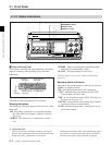
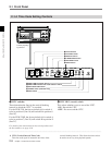
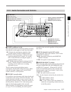
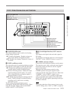
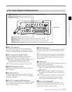
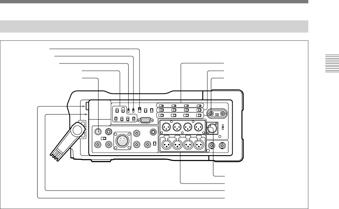
2-2-1 Audio Connectors and Controls
Audio connectors and controls
1 CONFI switch
2 CUE REC switch
3 CH-3/4 OUT switch
4 MONITOR SELECT switches
5 PHONE LEVEL control knob
6 +48 V switches (DVW-250P only)
7 CAMERA/LINE switches
8 Audio input level switches
9 AUDIO IN connectors
0 AUDIO OUT connectors
!¡ EARPHONE jack
!™ HEADPHONES jack
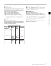
1 CONFI (confidence) switch
This selects the mode for monitoring during recording.
Note that this switch applies to both video and audio.
ON: Monitor the simultaneous playback of the
recorded signals from the confidence heads.
ECC (Error Correcting Codes): Monitor the input
signals unchanged (in E-E mode). If a serious
error is detected while recording the signals, a
warning indication is given.
OFF: Monitor the input signals unchanged (in E-E
mode). The RF envelope is monitored during
recording, and if a fault occurs a warning
indication is given.
The ON setting results in the highest power
consumption, and the OFF setting the lowest. When
using the unit with a battery pack, set the CONFI
switch to the ECC or OFF position.
2 CUE REC (record) switch
It is possible to mix the analog audio input signals and
record them on the analog cue track on the tape. This
switch determines whether or not to record on the cue
track during normal recording. When this switch is in
the ON position, channels 1 to 4 of the analog audio
input are mixed and recorded on the cue track.
When using the CUE DUB button on the front panel
(see page 2-3) for cue dubbing, the audio signal is
recorded on the cue track regardless of the position of
this switch.
3 CH-3/4 (channels 3 and 4) OUT switch
This selects the output from channels 3 and 4 of the
AUDIO OUT connectors.
MON: the signals selected by the MONITOR
SELECT switches
LINE: the signals of audio channels 3 and 4
4 MONITOR SELECT switches
These select the audio signals which can be monitored
using the EARPHONE jack, HEADPHONES jack,
and RFU OUT connector. When the CH-3/4 OUT
switch is in the MON position, these switches also
select the audio output from channels 3 and 4 of the
AUDIO OUT connectors.
CUE: the audio from the cue track
DA: Use the channels selected by the switch to the
right.
1/2: audio channels 1 and 2
3/4: audio channels 3 and 4
MIX: A mix of those of the four channels for
which the corresponding switches below are
in the ON position.