


Chapter 4 Recording
4-12 Chapter 4 Recording
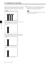
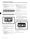
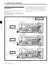
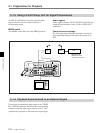
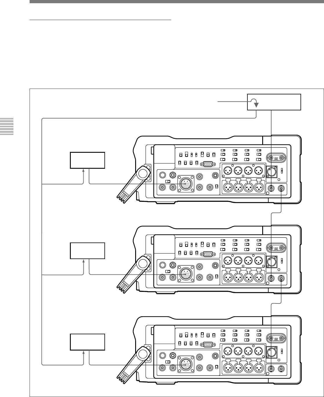
Example connections for time code locking
4-1 Preparations for Recording
Time code
generator
Reference signal
REF IN
REF OUT
TC IN
TC OUT
TC IN
TC OUT
TC IN
First DVW-250/250P
Second DVW-250/250P
Third DVW-250/250P
Camera
Camera
Camera
CAMERA
CAMERA
CAMERA
GENLOCK IN
GENLOCK IN
GENLOCK IN
Time Code Locking of Two or More DVW-
250/250P Units
Connect the DVW-250/250P units as shown in the
figure below.
In this case, on each of the DVW-250/250P units, set
the F-RUN/R-RUN switch to F-RUN and the CONFI
switch to ECC or OFF.
Then set the first DVW-250/250P so that it outputs the
time code generator signal from the TC OUT
connector. For example, when the “TC OUT” item is
set to “AUTO” (see previous page), the unit must be in
the E-E mode.