


Chapter 4 Recording
4-10 Chapter 4 Recording
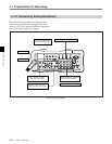
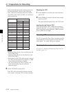
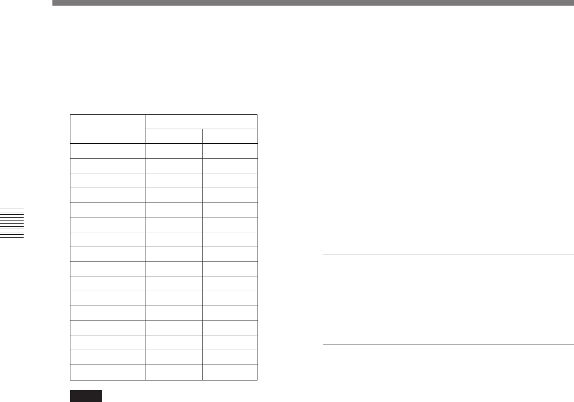
The relationship between the switch position and
the line represented is shown in the following
table. The factory default positions are 6 and 8
(for NTSC) and C and E (for PAL) for switches A
and B respectively.
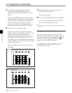
Switch position VITC insertion line No.
NTSC PAL
010—
110—
2129
31310
41411
51512
61613
71714
81815
91916
A2017
B—18
C—19
D—20
E—21
F—22
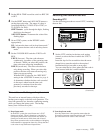
Notes
• Switch positions 0 and 1 are not effective for the
DVW-250P (PAL).
• Switch positions B to F are not effective for the
DVW-250 (NTSC).
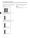
• Select lines for the VITC which are not occupied
by VITS (Vertical Interval Test Signal) or VIRS
(Vertical Interval Reference Signal).
• It is not possible to use line 11 (NTSC) or 8
(PAL) because these carry the reference
subcarrier signal.
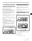
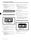
2 Set the VITC REC switch to ON.
The VITC will be recorded on the tape with the
video signals. Note that LTC is always recorded.
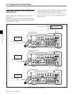
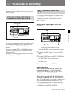
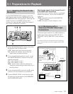
4-1 Preparations for Recording
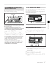
Checking the VITC
1 Set the DISPLAY switch by the status indication
panel to TC.
2 Set the DISPLAY switch in the time code setting
controls to VITC.
The status indication panel shows the VITC value.
Inserting the real time in VITC
Follow the procedure under “Setting the user bits to
reflect the real time” (see page 4-8), selecting VITC U-
BIT in step 2, and setting the REAL TIME record/set
switch to REC ON in step 4.
Recording LTC
The LTC (Longitudial Time Code), including user bits,
is automatically recorded together with the video and
audio signals. No switch settings are required.
Checking the time code and user bits
See Section 5-3 “Reading and Displaying Time Code and
User Bits” (page 5-5).