


Chapter 2 Location and Function of Parts
2-12 Chapter 2 Location and Function of Parts
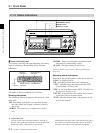
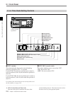
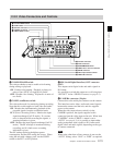
2-2 Connector Panel
5 PHONE LEVEL control knob
This adjusts the level of audio output to the
EARPHONE and HEADPHONES jacks.
6 +48 V switches (DVW-250P only)
For each of the four channels, these turn on or off the
48 V microphone phantom power supply to the
corresponding AUDIO IN connector. These switches
are only effective when the following selections are
made:
CAMERA/LINE switch: CAMERA position
Audio input level switch: –60 dB position
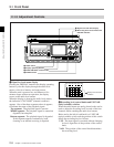
7 CAMERA/LINE switches
For each of the four audio channels, these select the
input.
CAMERA: the audio input to the CAMERA
connector (see next page)
LINE: the audio input to the corresponding AUDIO
IN connector
8 Audio input level switches
For each of the four channels, these select the audio
input level. There are three settings: –60, –20 and
+4 dBu.
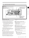
9 AUDIO IN connectors (XLR 3-pin)
These input up to four analog audio signals from
external microphones or other equipment.
0 AUDIO OUT connectors
These output analog audio signals for the four
channels to external equipment.
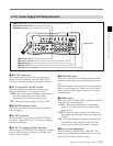
!¡ EARPHONE jack (stereo minijack)
Connect an earphone or stereo headphones equipped
with a stereo miniplug.
The MONITOR SELECT switches determine the
audio output.
When the WARNING indicator (see page 2-5) lights
or flashes, a warning sound is sent to the earphone.
!™ HEADPHONES jack (stereo standard jack)
Connect stereo headphones with an impedance of 8
ohms.
The MONITOR SELECT switches determine the
audio output.
When the WARNING indicator (see page 2-5) lights
or flashes, a warning sound is sent to the headphones.