63
Additional Information
GB
Using Optional Equipment
.
For Mono Equipment
Connect the phono plug to the L/G/S/I socket and select 5 input signal using the instructions above.
Refer to “Sound Adjustment” and select “Dual Sound” “A” on the sound menu screen (page 29).
1 Connect your equipment to the designated TV socket, as indicated on pages 61, 62 and 63.
2 Switch on the connected equipment.
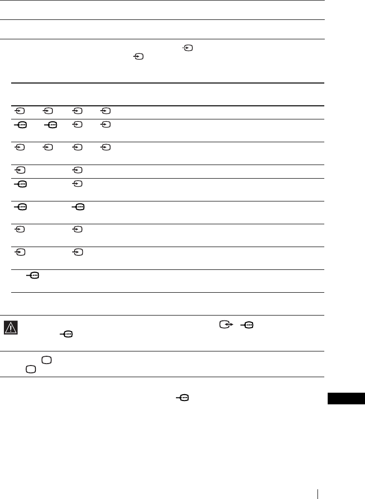
3 To watch the picture of the connected equipment, press repeatedly until the correct input symbol
appears on the screen. Also as you press repeatedly, the corresponding input select indicator on the
media receiver unit lights up.
Symbol Input select
indicator
Input Signals
1 or 2 1 or 2 • Audio / video input signal through the Scart connector H.
1 or 2 1 or 2 • RGB input signal through the Scart connector H. This
symbol appears only if an RGB source has been connected.
3 or 4 3 or 4 • Audio / video input signal through the Scart connector I or
N.
33• S Video input signal through the Scart connector I.
44• RGB input signal through the Scart connector N. This
symbol appears only if an RGB source has been connected.
55• Component input signal through the Y, P
B/CB, PR/CR jacks
L and Audio input signal through K.
66• Video input signal through the phono socket F and Audio
input signal through G.
66• S Video input signal through the S Video input jack E and
Audio signal through G.
PC PC • RGB input signal through the 15-DSub connector B and
audio input signal through C.
MEMORY
STICK
MEMORY
STICK
• Data input from a “Memory Stick” inserted in “Memory
Stick” slot A.
If your DVD recorder is connected to both the Scart connector 4/ and the Y, P
B/CB, PR/
C
R jacks of 5, select the input connector by using “AV4 Input Select” option in the “Feature”
menu (page 35).
4 Press the button on the remote control to return to the normal TV picture.
The indicator on the media receiver unit lights up.
S
S S
