


– 5 –
1. OUTLINE
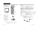
• The units in this manual contain a self-diagnostic function.
• If an error occurs, the STANDBY lamp will automatically begin to flash.
The number of times the lamp flashes translates to a probable source of the problem. A definition of the STANDBY lamp
flash indicators is listed in the instruction manual for the user’s knowledge and reference.
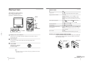
• If an error symptom cannot be reproduced, the remote commander can be used to review the failure occurrence data
stored in memory to reveal past problems and how often these problems occur.
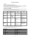
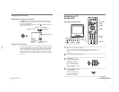
2. DIAGNOSTIC TEST INDICATORS
• When an errors occurs, the STANDBY lamp will flash a set number of times to indicate the possible cause of the problem.
If there is more than one error, the lamp will identify the first of the problem areas.
• Result for all of the following diagnostic items are displayed on screen. No error has occured if the screen displays a “0”.
Diagnostic
Item
Description
• Power does not
turn on
No. of times
STANDBY lamp
flashes
Does not light
Self-diagnostic
display/Diagnostic
result
—
Probable
Cause
Location
• Power cord is not plugged
in.
• Fuse is burned out F901
Detected
Symptoms
• Power does not come on.
• No power is supplied to the
TV.
• AC power supply is faulty.
Note 1: If a + B overcurrent is detected, stoppage of the vertical deflection is detected simultaneously.
The symptom that is diagnosed first by the microcontroller is displayed on the screen.
Note 2: Refer to screen (G2) Adjustment in section 3-4 of this manual.
SELF DIAGNOSTIC FUNCTION
• FBT
• Q802 (H OUT) shorted
2 : 0 or
2 : 1
4 : 1
2 times
4 times
5 times
• Vertical deflection
stopped
• White balance
failure (no
PICTURE)
• +B overcurrent
(OCP) or
overvoltage
(OVP)
• Has entered standby state
after horizontal raster.
• Vertical deflection pulse is
stopped.
• Horizontal deflection
stopped.
• Power line is shorted or
power supply is stopped.
4 : 0
or
4 : 1
• IC501
• IC301 !¢ pin
• IC606
• Q802 (H OUT) shorted
• Q803
• Q608
• R803 open
5 : 0
or
5 : 1
• On standby state.
• Load on power line is
shorted
(at the same time 4 : 1 on
display).
at the same
time
(Note 1)
•CRT
• IC301
• IC701 - IC703, Q701
(CV board)
• G2 is improperly adjusted.
(Note 2)
• No raster is generated.
• CRT cathode current
detection reference pulse
output is small.
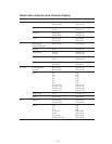
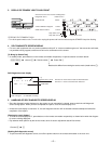
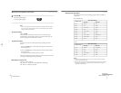
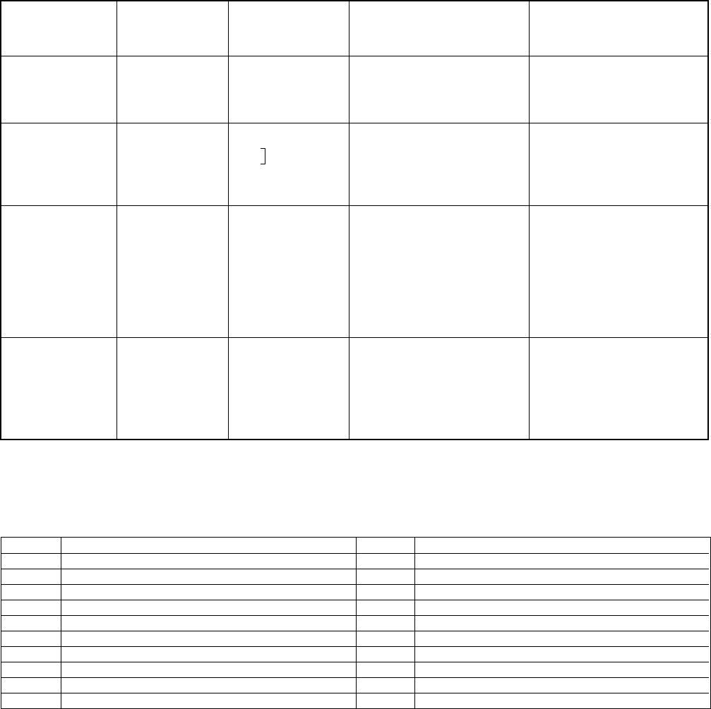
Code Coutents
00h NO EMG
10h CAM encode NG during unloading
11h CAM encode NG during unloading
12h CAM encode NG at intial
20h T reel NG during unloading
21h S reel FG NG
22h T reel FG NG
23h S reel FG NG
24h T reel FG NG at initial
25h S reel FG NG at initial
Code Coutents
30h Capstan FG NG at initial
31h Capstan FG NG
40h Drum FG NG
41h Drum FG NG at initial
42h Drum FG NG
43h Drum PG NG
44h Drum PG NG
50h DEW
60h FL NG
70h DEW eject NG
• VCR EMG code List