


– 100 –
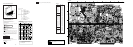
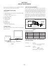
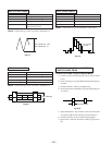
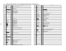
REC Y LEVEL CHECK
Mode E-E(SP)
Signal No signal
Measurement Point MA10 board IC802 !•pin
Measurement Equipment Oscilloscope
Specified Value 240±70mVp-p(NTSC)
260±70mVp-p(PAL)
Check: Confirm the Vp-p of the waveform is 220±70mVp-p.
Fig.3-7
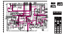
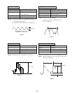
REC CHROMA CHECK
240 ± 70mVp-p (NTSC)
260 ± 70mVp-p (PAL)
Mode REC(SP)
Signal Color bar
Measurement Point MA10 board IC802 !¢pin
Measurement Equipment Oscilloscope
Specified Value 350±60mVp-p
Check: Confirm the Vp-p of the waveform is 350±60mVp-p.
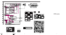
PB Y LEVEL CHECK
Mode PB
Signal Color bar
Measurement Point MA10 board Q830 emitter
Measurement Equipment Oscilloscope
Specified Value 1.0±0.1Vp-p
Check: Confirm the Vp-p of the waneform is 1.0±0.1Vp-p.
SWITCHING LOCATION ADJUSTMENT
WHEN CHANGE DRUM
1.VIDEO SWITCHING LOCATION ADJUSTMENT
1) Connect between CN1004 pin 2 and pin 6 on MA10
board.
2) Insert switching over up tape(KRV-23PS)and push the play
back key.
3) Push the channel + and-keys simultaneously.
4) Short instant between CN1004 pin 1 and pin 6.(LED goes
on and off)
Less than 30µsec.
Fig.3-8
350 ± 60mVp-p
Fig.3-9
1.0 ± 0.1Vp-p
(Y Level)
5) Adjust the channel+/- keys of the set so that waveform width
of CN702 pin 2 become minimum.(less than 30µsec.)
6) Push the pause key of the set.(LED wink disappear)
7) Remove the connection between CN1004 pin 2 and pin
6.
Fig.3-10