


– 68 –
SECTION 3
SET-UP ADJUSTMENTS
• The following adjustments should be made when a complete
realignment is required or a new picture tube is installed.
• These adjustments should be performed with the rated
power supply voltage, unless otherwise noted.
The PICTURE and Brightness controls should be set as follows
unless otherwise noted:
PICTURE control................ standard
BRIGHTNESS control.......... standard
Perform the adjustments in the following order:
1. Beam Landing
2. Convergence
3. Focus
4. Screen (G2)
5. White Balance
6. Picture Distortion
Note: Test Equipment Required.
1. Color bar/Pattern Generator
2. Degausser
3. Oscilloscope
Preparation:
• In order to reduce the influence of external magnetic
forces on the picture tube, face the TV set in an easterly
or westerly direction.
• Turn the power switch for the unit ON and erase the magnetic
force using a degausser.
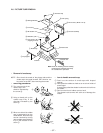
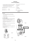
3-1. BEAM LANDING
1. Receive PAL MONOSCO signal, make [picture] to maximum.
2. Set service mode to VP38 (RON) = "00", VP39 (GON) = "01",
VP40 (BON) = "00" and make all green pattern.
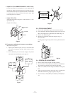
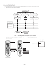
3. Shift the DY Assy to full of front side and rotate purity magnet
and make green to center. (Fig.3-1 to 3-3)
4. Rotate DY Assy to right and the left and screen align to
horizontal.
5. Shift slowly the DY Assy to back side and set raster to get full
green. (Fig.3-3)
6. Fix roughly the DY Assy by the stopper.
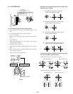
7. When the landing at the corners is not correct, adjust by using
disk magnets. (Fig.3-4)
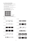
8. Set service mode to VP38 (RON) = "01", VP39 (GON) = "01",
VP40 (BON) = "01".
Purity control
B
G
R
Fig.3-1
Fig.3-2
Fig.3-3
ab
cd
b
d
a
c
Purity control
corrects this area.
Disk magnets or rotatable
disk magnets correct these
areas (a-d).
Deflection yoke positioning
corrects these areas.
Fig.3-4