


– 95 –
TABLE OF CONTENTS
Section Title Page Section Title Page
[ VIDEO SECTION]
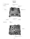
1. GENERAL
1-1. INTERNAL VIEWS ............................................... 96
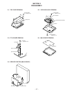
2. DISASSEMBLY
2-1. Top Cover Removal................................................. 97
2-2. VCR Block Assy Removal ...................................... 97
2-3. FF10 Board Removal .............................................. 97
2-4. MA10 Board Removal ............................................ 97
2-5. Service Position (MA10 Board) .............................. 97
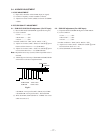
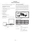
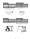
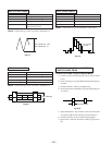
3. CIRCUIT ADJUSTMENTS .................................... 98
4. INTERFACE, IC PIN FUNCTION DESCRIPTION
4-1. µ-COM Poart Function Description
(MA10 Board IC001) .............................................. 101
4-2. System Control-Video Block Interface
(MA10 Board IC402) .............................................. 102
4-3. System Control-Servo Peripheral Circuit Interface
(MA10 Board IC402) .............................................. 102
4-4. System Control-Mechanism Block Interface
(MA10 Board IC402) .............................................. 103
4-5. System Control-System Control Peripheral Circuit Interface
(MA10 Board IC402) .............................................. 103
4-6. System Control-Audio Block Interface
(MA10 Board IC402) .............................................. 103
4-7. Servo/System Control Port Function Description
(MA10 Board IC402) .............................................. 104
5. DIAGRAMS
5-1. Block Diagrams....................................................... 105
5-2. Circuit Boards Location .......................................... 107
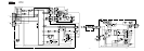
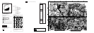
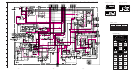
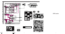
5-3. Printed Wiring Boards and Schematic Diagrams .... 108
• MA10 (1/3) Board .................................................. 111
• MA10 (2/3) Board .................................................. 115
• MA10 (3/3) Board .................................................. 119
• FF10 Board ............................................................. 121
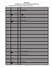
5-4. Semiconductors ....................................................... 122
6. EXPLODED VIEWS
6-3. Mechanism Deck Assembly (1) .............................. 126
6-4. Mechanism Deck Assembly (2) .............................. 127
6-5. Mechanism Deck Assembly (3) .............................. 128
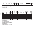
7. ELECTRICAL PARTS LIST ...................................... 135