


– 98 –
SECTION 3
CIRCUIT ADJUSTMENTS
Necessary items and indications for total adjustment of electric
circuit of this unit will be described in this chapter.
[ INSTRUMENTS TO BE USED ]
1) Color TV
2) Signal or dual trace type oscilloscope, band more than 30 MHz,
delay, as provided.
3) Frequency counter (4 digits or more)
4) PAL pattern generater
5) Digital voltmeter
6) Audio level meter
7) Audio generator
8) Attenuator
9) Distortion meter
10) Alignment tape
Part code : H7099052H (MH-2)
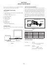
[ CONNECTION ]
Unless otherwise specified, connect and adjust the measurement
equipment as follows.
[ SPECIFIED INPUT/OUTPUT LEVEL IMPEDANCE ]
Input/Output terminal
Video input Pin jack
Input signal : 1Vp-p, 75Ω, unbalanced
Sync negative
AUDIO LINE IN Pin jack
Input level : -7.5dBs
(0dBs=0.775Vrms)
Input impedance : More than 47kΩ
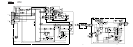
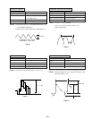
[ SET-UP FOR ADJUSTMENT ]
The video signal from the pattern generator is used as adjustment
signal for electrical adjustment. This video signal should meet the
requirement. Connect the oscilloscpe to the video input terminal
on the MF 1 board and make sure that the amplitudes of sync signal
of video signal, video portion and burst signal are flat at
approximately 0.3, 0.7 and 0.3 V, respectively, and that the level
ratio of the burst signal and “red siganl” are 0.30 : 0.66, Fig.3-2
shows video signals (color bars) used in adjusting the electrical
adjustment.
Pattern generator
VIDEO LINE OUT (75Ω)
VIDEO INPUT
Fig.3-1
Fig.3-2
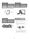
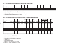
Alignment Tape (MH-2)
Time Video signal Audio signal
1 10 minutes Starir-step 6kHz
2 5 minutes - 3kHz
3 10 minutes Color bar 1kHz
4 3 minutes RF sweep -
Approx.
0.7V
Burst signal
(To be flat)
White (approx. 100%)
Horizontal sync signal
Red
Approx.
0.3V
Approx.
0.3V