


– 70 –
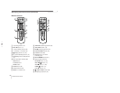
• Adjust TLH. (TLH CORRECTION PIECE : 4-057-714-01)
Correct horizontal mis-convergence of X axis' right and left
red and blue. When red is outside and view from DY neck side,
insert TLH correction piece to rightside (TLH+) and when blue
is outside and also view from DY neck side, insert TLH
correction piece to left (TLH-).
• Adjust YCH. (YCH)
Adjust the horizontal convergence of red and blue of Y axis'
up and down part.
(Adjust with tracking)
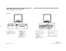
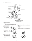
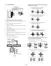
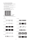
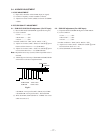
(2) Convergence adjustment of screen surroundings.
(Dynamic convergence)
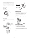
1. Adjust by the deflection yoke (swivel) to screen both sides
cross mis-convergence become finest whole screen.
(Fig.3-7)
2. Fix the deflection yoke to insert the wedge to the picture
tube funnel and the deflection yoke. (Fig.3-8)
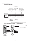
YCH
RV701
CV board
TLH
TLH correction
piece
Fig.3-6
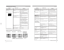
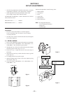
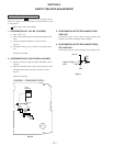
3-3. FOCUS ADJUSTMENT
1. Receive PAL MONOSCO signal, with standard condition.
2. Focus adjustment should be balanced whole picture area (not
detail), and adjust focus by [FOCUS] VR of FBT. (Fig.3-9)
3. Receive ALL WHITE signal.
4. Magenta ring should be within limit sample. (Fig.3-9)
<If out of limit>
Tracking adjust magentaring and the focus by [FOCUS] VR of
FBT.
B
B
B
B
BB
B
B
B
B
B
B
G
G
G
G
G
G
G
G
G
G
G
G
R
R
R
R
R
R
R
R
R
R
R
R
Fig.3-7
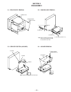
a
a
b
b
c
c
d
d
a-d : screen-corner
misconvergence
Fig.3-8
3-4. SCREEN (G2) ADJUSTMENT
1. Receive white signal and make standard condition.
2. Set service data to VP38 (RON), VP39 (GON), VP40 (BON) =
"00" and take care that the screen become pitch-dark.
3. Add 175 ± 1.0VDC external voltage to cathodes of red, green,
blue.
4. Adjust to obtain just before retrace line goes out (The point
where the retrace line is going to appears). (Fig.3-9)
5. Set service data to VP38 (RON), VP39 (GON), VP40 (BON) =
"01".
Focus
Screen
Fig.3-9