


– 77 –
5-4. A BOARD ADJUSTMENT
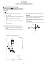
1. H OSC ADJUSTMENT
1) Input select should be selected LINE input (no signal).
2) Connect a frequency counter to TP801 (A board).
3) Adjust service data "VP42" (HOSC) to become 15.690kHz
± 25Hz.
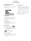
2. PICTURE QUALITY ADJUSTMENT
2-1. SUB HUE, SUB COLOR adjustment. (For RF input)
1) Receive RF NTSC COLOR BAR signal (B OUT signal).
2) Color Condition
• Color .................. 50%
• HUE center ........ 50%
• Picture ............... 80%
* H white condition is "OFF" (VP36 : DYCL "= 00")
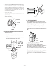
3) Adjust service data (VP28 : SHUE) for CN308 6 pin B
OUT waveform shown V
B2
= V
B3
(SUB HUE).
4) Adjust service data (VP27 : SCOL) for CN308 6 pin B
out waveform shown V
B1
= V
B4
(SUB COLOR).
Note : Repeat the above steps 2) and 3) untill an optimum value is
obtained.
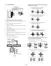
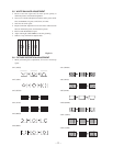
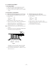
5) Add the figure of each step of SUB HUE and SUB COLOR
shown below to the above adjustment data.
SUB COLOR
SUB COLOR 70mV or less
SUB HUE 110mV or less
SUB HUE
VB1 VB2
VB3
VB4
• SUB HUE : From just flat VP28 : SHUE (TV) 0 STEP
• SUB COLOR : From just flat VP27 : SCOL 0 STEP
6) Write SUB HUE, SUB COLOR for "VIDEO" the values
which are same as 4).
2-2. SUB HUE adjustment (For LINE input)
1) Input the NTSC COLOR BAR Signal to LINE INPUT.
2) Color Condition
• Color .................. 50%
• HUE center ........ 50%
• Picture ............... 80%
* H white condition is "OFF" (VP36 : DYCL = "00")
3) Adjust service data (VP50 : VSHU)for CN308 6 pin B
OUT waveform shown V
B2
= V
B3
.
4) Write SUB HUE (for LINE INPUT)
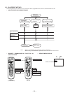
Fig.5-1