


– 72 –
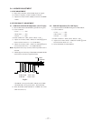
CONFIRMATION OF HOLD-DOWN
When the parts with a , mark on the circuit diagram shown
below are replaced, confirm the matters described in items 1. and
2. shown below.
: PM601, R614, C614, IC607, R638
1. CONFIRMATION OF +B LINE (A BOARD)
1) Input 110 V AC.
2) Receive DOT HATCH signal and adjust PIX, BRT to mini-
mum.
3) Connect the digital multimeter to ⊕ line of C632.
(Fig.4-2)
4) Confirm the voltage value of +B line corresponds like be-
low.
Less than 137.5V DC
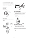
2. CONFIRMATION OF HOLD-DOWN (A BOARD)
1) Receive monoscope signal and adjust PIX, BRT, VOL to
standard.
2) Input the undermentioned voltage to between C632 + side
and GND, then check the protector function to works.
(Fig.4-1)
Less than 142.5V DC
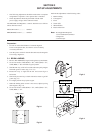
SECTION 4
SAFETY RELATED ADJUSTMENT
3. CONFIRMATION AFTER EXCHANGED IC607
AND R638
Confirm the voltage value of +B line voltage satisfying with
standard value when exchanged IC607 and R638.
4. CONFIRMATION AFTER EXCHANGED PM601,
R614 AND C614
Confirm the protection circuit satisfying with standard value.
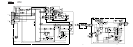
Fig.4-1
+2
–0
-
+
+
+
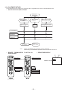
A BOARD – COMPONENT SIDE –
FBT
digital
multimeter
1
8
I
O
R614
PM601
C632
IC607
C614
R638
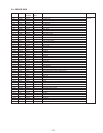
Fig.4-2
D803
R615
FBT
+B Line
C632
Applied voltage
point