


1-5
PFM-42B1, PFM-42B1E
8
(GB)
Location and Function of Parts and Controls
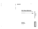
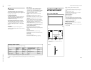
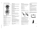
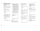
1 (standby) Switch / Indicator
Section
1 1 (standby) switch
Press to turn on the monitor. Press again to go back to
the standby mode.
2 STANDBY indicator
Lights up in red in the standby mode.
When the STANDBY indicator flashes, see
“Self-diagnosis
Function” on page 35 (GB).
3 ON indicator
Lights up in green when the monitor is turned on.
4 Remote control detector
Receives the signal from the Remote Commander.
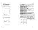
Control Button Section (Rear)
1 MENU button
Press to make the menu appear. When the menu is
displayed on the monitor screen, press to return to the
previous menu level. To clear the menu display, press
this button repeatedly until the menu disappears.
2 v/ V buttons
Press to move the cursor (B) to an item or to adjust a
value in a menu.
3 ENTER button
Press to select the desired item from the menu
displayed.
2
1
3
4
3
1
2
9
(GB)
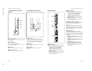
Location and Function of Parts and Controls
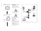
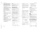
2 INPUT2 connectors
RGB/YUV (D-sub 15-pin): Connects to the RGB
signal or component (YUV) signal output of a
computer or a piece of video equipment.
This monitor also accepts an HD analog
component (Y/P
B
/P
R
) signal. See “Pin
assignment” on page 39 (GB) when inputting a
component signal.
AUDIO (Stereo minijack): Inputs an audio signal.
Connects to the audio output of a computer or a
piece of video equipment.
3 AUDIO OUT jack (Stereo minijack)
From among the audio signals input at the audio input
jacks, outputs the audio signal displayed on the
monitor screen.
4 REMOTE (RS-232C) connector (D-sub 9-pin)
This connector allows remote control of the monitor
using the RS-232C protocol. For details, contact your
authorized Sony dealer.
5 VIDEO connectors
The PFM-42B1E is not equipped with VIDEO
connectors. For the PFM-42B1E, composite video and
Y/C input can be input to the monitor when the BKM-
B10 video input adaptor (not supplied) is installed in
the monitor.
COMPOSITE IN (BNC-type): Connects to the
composite video signal output of a piece of video
equipment.
COMPOSITE OUT (BNC-type): Connects to the
composite video signal input of a piece of video
equipment.
Y/C IN (Mini DIN 4-pin): Connects to the Y/C
signal output of a piece of video equipment.
AUDIO IN (Stereo minijack): Inputs an audio
signal. Connects to the audio output of a piece of
video equipment.
Connector Panel
1 INPUT1 connectors
RGB/YUV (D-sub 15-pin): Connects to the RGB
signal or component (YUV) signal output of a
computer or a piece of video equipment.
This monitor also accepts an HD analog
component (Y/P
B
/P
R
) signal. See “Pin
assignment” on page 39 (GB) when inputting a
component signal.
AUDIO (Stereo minijack): Inputs an audio signal.
Connects to the audio output of a computer or a
piece of video equipment.
1
2
3
4
5