


1-6
PFM-42B1, PFM-42B1E
10
(GB)
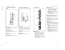
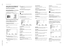
Location and Function of Parts and Controls
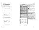
Remote Commander RM-42B
1 POWER ON switch
Press to turn on the monitor.
2 DISPLAY button
Displays the input signal information and the time at
the top of the monitor screen. Press again to clear it.
3 INPUT1 button
Selects the signal input from the INPUT1 connectors.
4 INPUT2 button
Selects the signal input from the INPUT2 connectors.
5 VIDEO button
Selects the signal input from the COMPOSITE IN
connector or Y/C IN connector from among the
VIDEO connectors.
6 OPTION button
Selects the signal input from the optional adaptor
when you install it in the unit.
7 ASPECT button
Changes the aspect ratio of the picture.
8 H SHIFT button
Adjusts the horizontal centering. Press this button and
then adjust the horizontal centering with the SELECT
+M/–m button qj.
9 V SHIFT button
Adjusts the vertical centering. Press this button and
then adjust the vertical centering with the SELECT
+M/–m button qj.
0 H SIZE button
Adjusts the horizontal picture size. Press this button
and then adjust the horizontal picture size with the
SELECT +M/–m button qj.
qa V SIZE button
Adjusts the vertical picture size. Press this button and
then adjust the vertical picture size with the SELECT
+M/–m button qj.
qs STANDBY button
Press to turn the monitor to the standby mode.
qd RGB/YUV button
Press to select the format matching that of the input
signal connected to the INPUT1 or INPUT2
connector. Each press toggles between RGB and
YUV.
qf S/VIDEO button
Press to select the signal input from the COMPOSITE
IN connector or Y/C IN connector from among the
VIDEO connectors. Each press toggles between
COMPOSITE IN and Y/C IN.
qg Number buttons
Press to enter the index number.
qh ID MODE (ON/SET/OFF) buttons
Press the ON button to make an index number appear
on the screen. Then enter the index number of the
monitor you want to operate using the number buttons
qg and press the SET button. After you finish the
operation, press the OFF button to return from the ID
mode to the normal mode.
For details about the index number, see
“Operating a
Specific Monitor With the Remote Commander
” on page 35
(GB).
qj SELECT +M/–m button
Press to move the cursor (B) to an item or to adjust a
value in a menu.
0
qj
6
3
2
4
5
1
7
qh
qk
ql
qd
qf
qs
qg
8
w;
9
wa
qa
11
(GB)
Location and Function of Parts and Controls / Caution
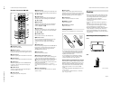
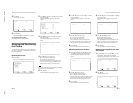
Be sure to
install the
negative <
–
end first.
qk MENU button
Press to make the menu appear. When the menu is
displayed on the monitor screen, press to return to the
previous menu level. To clear the menu display, press
this button repeatedly until the menu disappears.
ql ENTER button
Press to select the desired item in a menu.
w; BRIGHT +/– button
Adjusts the brightness.
wa CONTRAST +/
– button
Adjusts the contrast.
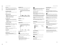
Installing batteries
Insert two size AA (R6) batteries in correct polarity.
e
E
E
e
•In normal operation, batteries will last up to half a
year. If the Remote Commander does not operate
properly, the batteries might be exhausted sooner.
Replace them with new ones.
•To avoid damage from possible battery leakage,
remove the batteries if you do not plan to use the
Remote Commander for a fairly long time.
When the Remote Commander does not work
Check that the STANDBY indicator lights up and the
REMOTE MODE in the REMOTE menu is not set to
OFF. The Remote Commander operates the monitor
only when both of the two conditions below are met.
•The monitor is turned on, or it is in the standby
mode.
•The REMOTE MODE in the REMOTE menu is set
to TV or to PJ.
For details about the REMOTE MODE, see
“REMOTE
menu” on page 16 (GB).
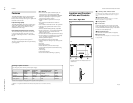
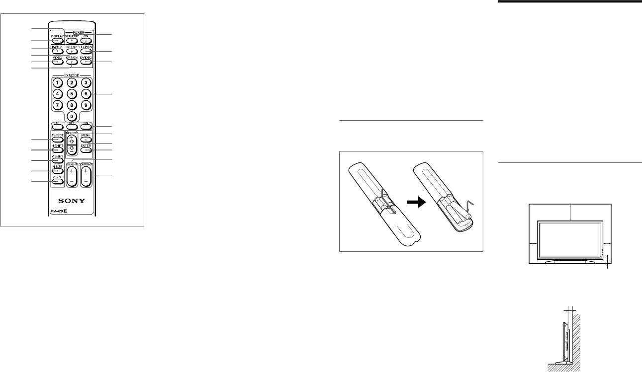
Caution
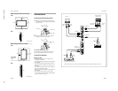
•When you use the monitor, make sure there is more
space between the edges of the unit and other walls
or the ceiling than that shown in the figure below.
This will allow for proper ventilation.
•The ambient temperature must be 0
°C to +35 °C
(32 °F to 95 °F).
•Use the SU-42B monitor stand (not supplied) as a
stand.
•The wall should be reinforced to bear at least five
times the weight of the monitor (approx. 29.4 kg)
plus the wall bracket you are planning to use.
•Regarding installation of hardware such as brackets,
screws, and bolts, we cannot specify what to use
because actual installation is up to the authorized
local dealers. For installation, consult with qualified
Sony personnel.
When using the stand (not supplied)
Front
20 (7
7
/
8
)
10
(4)
10
(4)
6.5 (2
5
/
8
)
Wall
Floor
Wall Wall
Side
Floor
Wall
10 (4)
Units: cm (inches)