


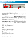
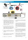

Layout of the Rear Panel
1) CH1 ~ CH4 (Video Inputs): These are the four
camera inputs, labelled as per their channel in the
DVR’s interface. Thus, plug the camera you want
to be associated with Channel 1 into the port
marked CH1 and so on.
2) Video Outputs: This sends a composite video
signal out of the DVR. Each of the two ports can
be connected to separate monitors. The output
marked MAIN will show the main DVR interface
(all channels accessible plus menus, unless you’ve
configured the DVR to use the VGA as the main
output).
3) Audio Inputs (CH1 ~ CH4): Four labelled
audio inputs. These will accept standard line-level
signals (<1V) and can be assigned to channels
later.
4) Audio Output: Two mono audio output
channels. These output a standard ‘line-level’
signal, and can easily be connected to the audio
inputs on a television or stand-alone audio
device.
5) VGA Output: For connection to a VGA
monitor. This will display the same image as the
MAIN video output at a selectable resolution
between 800 x 600, to a maximum of 1400 x
900.
6 Above) USB Mouse Port: For connecting the
included USB mouse (other standard USB mice will
also work). This port will not accept a USB flash
drive – this port will work with a mouse only.
6 Below) USB Backup Port: For connecting a
USB flash drive for the purposes of backing up
footage.
7) RS485 Connections: This is the serial
communication port, used primarily to connect
PTZ (pan, tilt, zoom) devices.
8) Power Connection: For supplying power to
the DVR. Use only the supplied power adaptor,
and do NOT change or modify it in any way.
Modifications to your power supply radically
increases the risk of electrocution or fire, and will
immediately void your warranty.
9) LAN Port: To connect an Ethernet cable,
allowing the DVR to be connected to a local area
network. This network, in turn, can be used to
give the DVR a connection to the Internet.
7
8
5
7 9 6 2 1 4 3