


AXIS M1143–L
Technical Specifications
Function/group
Item
Specifications
Installation,
management and
maintenance
AXIS Camera Management tool on CD and web-based configuration
Configuration of backup and restore
Firmware upgrades over HTTP or FTP, firmware available on www.axis.com
Casing
Aluminium and PC/ABS
Color: White NCS S 1002-B
Processor,
memory
Ambarella, 256 MB RAM, 128 MB Flash
Battery backed-up real-time clock
Power
Power over Ethernet IEEE 802.3af Class 2 (max. 6.49W)
IR illumination Highly efficient IR LEDs with adjustable intensity and angle of illumination. Range of
reachupto25m
Connectors
RJ-45 10BASE-T/100BASE-TX 1 alarm input and 1 output
Local storage
Micro SD/SDHC memo ry card slot (card not included)
Operating
conditions
0 °C to 40 °C (32 °F to 122 °F), humidity 20 - 80% RH (non-condensing)
Storage
temperature
-20to60°C(-4to140°F)
Approvals
CE: Emission: EN55022:2006+A1 Class B Harmonics: EN61000-3-2 Flicker: EN61000-3-3
Immunity: EN55024, EN61000-6-1, EN61000-6-2 Safety: EN60950-1+A11
FCC: FCC Part 15, Subpart B, Class B demonstrated by compliance with EN55022 (CISPR
22)
Japan: VCCI-2008, Class B, ITE • C-tick AS/NZS CISPR 22, demonstrated by compliance
with EN55022 (CISPR 22)
Canada: ICES-003 Canadian ICES-003, Class B digital, demonstrated by compliance
with EN55022 (CISPR 22)
Korea: Emission: K N2 2 Immunity: KN 24 UL: cUL, usUL UL-60950-1 IR: SS-EN-62471
Dimensions
46 x 75 x 115 mm (1.8" x 3.0" x 4.5")
Weight
250g (0.21 lb.)
Included
accessories
Stand, Lever tool, Installation Guide, CD including installation tools and other software,
Windows decoder 1-user license
General
Video
management
software (not
included)
AXIS Camera Station - V
ideo management software for viewing and
recording up to 100 camer as. For more software application via partners, see
www.axis.com/products/video/software/
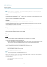
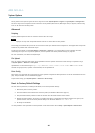
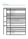
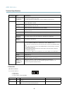
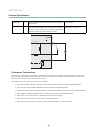
Connectors
I/O terminal connector
4–pin terminal block for:
• Digital Input
• Digital Output
• Auxiliary power and ground (GND)
1 2 3 4
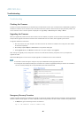
Function Pin Notes
Specifications
GND
1
Ground
3.3 V DC Power
2
Can be used to pow er auxiliary equipment.
Note: This pin can only be used as power out.
Max load = 50 mA
51