


7
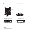
AXIS P7701 - Hardware overview
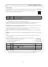
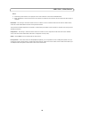
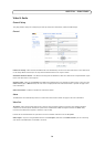
The following connection diagram gives an example of how to connect an auxiliary device to the AXIS P7701.
1
2
Push to trigger video select
Switch
3 video input
4 Unused
AXIS P7701
3.3V max 250mA
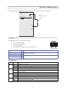
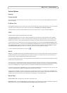
RS-422/RS-485 connector - Two 2-pin terminal blocks for RS-485/422 serial interface used to control auxiliary equipment,
e.g. PTZ devices.
The RS-485/422 serial port can be configured to support:
RS-485/422
RS-485/422
RX/TX
RX/TX
1 2 3 4
TX
• Two-wire RS-485 half duplex
• Four-wire RS-485 full duplex
• Two-wire RS422 simplex
• Four-wire RS422 full duplex point to point communication
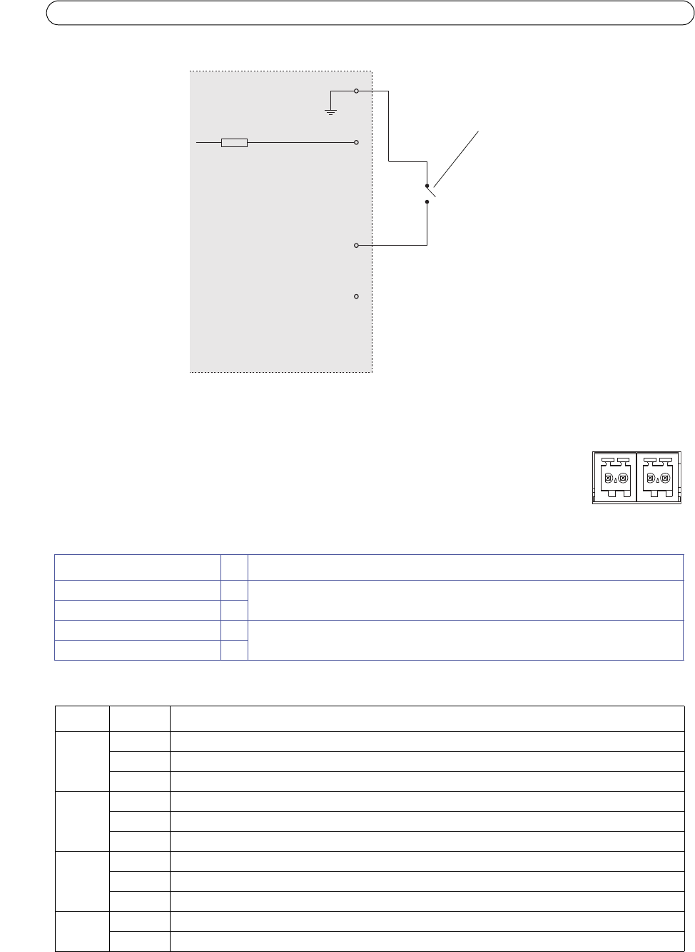
RS-485/422 RX/TX A 1 (RX) For full duplex RS-485/422
(RX/TX) For half duplex RS-485
RS-485/422 RX/TX B 2
RS-485/422 TX A 3 (TX) For full duplex RS-485/422
RS-485/422 TX B 4
LED indicators
Video Green Encoder/Camera is connected.
Amber Steady when connecting t
o an encoder/camera.
Red No encoder/camera is connected.
Network Green Steady for connection to a 100 Mbit/s network. Flashes for network activity.
Amber Steady for connection to 10 Mbit/s network. Flashes
for network activity.
Unlit No network connection.
Status Green Steady green for normal operation.
Amber Steady during startup, during reset to factory
default or when restoring settings.
Red Slow flash for failed upgrade.
Power Green Normal operation.
Amber Flashes green/amber during firmware upgrade.
Function Pin Notes
LED Color Indication