


5. Cabling of an ILite display
5.2 Power cabling of an ILite display
Power boxes
Barco provides several types of power boxes. Depending on the size of the ILite display you can choose to use the mono phase
power box or the custom made power box or the rental power box. The type of power box, does not influence the power cabling of
the ILite display. See installation manual of the concerned power box for installation instructions.
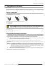
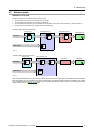
Plug types of power cables
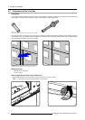
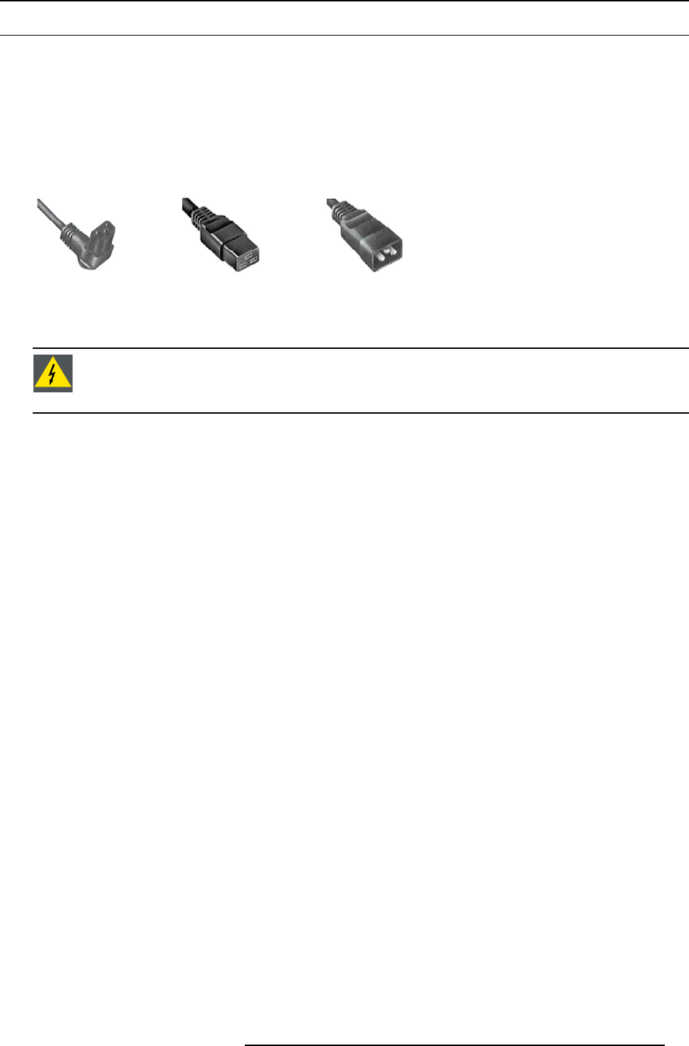
The illustration below shows the three different kinds of plugs used onILite power cables. Note that theILite power split cable has all
three different plug types (C13, C19 and C20).
AB C
Image 5-2
A C13 plug. Fits into the C14 power socket of the ILite tile.
B C19 plug (female).
C C20 plug (male).
WARNING: Risk of electric shock / Risk of fire: To protect against risk of
fire caused by overloading of power
cables, MAXIMUM six (6) tiles may be connected in parallel. Each power source cable supplying maximum
six (6) tiles should be protected by a circuit breaker or fuses rated 16 A / 250 VAC (15 A / 250 VAC in the USA
and Canada). Note that one ILite tile requires 200-240 VAC, 50-60 Hz
,1.45ampsat230VAC.
Necessary parts
• Power box(es) with matching cables.
• Power split cables.
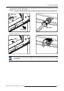
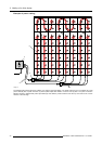
How to realize the power cabling of an ILite display ?
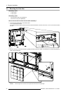
1. Install the power box nearby the ILite display. Ensure the power box provides as much power circuits as required to energize the
display ina safemanner. If necessary, install severalpowe
r boxes. See manualof theused powerbox forinstallation instructions.
2. Connect a power source cable coming from the power box with the C20 plug of an ILite power split cable.
Note: Dependingon the typeof used power box,a multi powercable in combinationwith a spiderconnector is insertedbetween
the power box and the power source cable leading to the power split cable of the first ILite tile. See manual of the used
power box to realize the cabling between power box and ILite display.
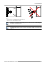
3. Connect the C13 plug of the power split cable with one of the tiles in the LED-display. Start with a tile at the bottom.
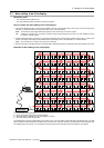
4. Connect another power split cable with the previously installed power split cable and plug the C13 plug into the power socket of
the tile above.
5. Repeat step 4 until maximum six (6) tiles are connecte
d with the same power source cable coming from the power box.
Warning: Risk of electric shock / Risk of fire: To protect against risk of fire caused by overloading of power cables, MAXI-
MUM six (6) tiles may be connected in parallel. Each power source cable supplying maximum six (6) tiles should be
protected by a circuit breaker or fuses rated 1
6 A / 250 VAC (15 A / 250 VAC in the USA and Canada). Note that
one ILite tile requires 200-240 VAC, 50-60 Hz, 1.45 amps at 230 VAC.
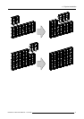
Tip: Create as much as possible vertical power branches of six (6) tiles high. Only include tiles of neighboring columns in
case the power branch is less than six (6) tiles high.
6. Repeat from step 2 until all ILite tiles are pr
ovided with power.
R5976522 FIXED ILITE DISPLAY 17/11/2006
39