


5. Cabling of an ILite display
5.3 Data cabling of an ILite display
Necessary parts
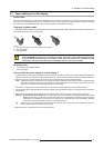
• One short data linking cable per tile.
• One long data linking cable (maximum 5 meter) per digitizer.
How to realize the data cabling of an ILite display ?
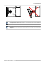
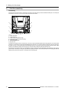
1. Connect the data linking cable, coming from the digitizer, with one of the two data ports on the re-sync unit of the first tile in the
data path. The first tile must be one of the tiles in the corner of the ILite display.
Note: The maximum cable length between the digitizer and the first tile may not exceed 5 meter.
Tip: Use Barco’s “Compact Link” or “Fiberlink” system to bridge a distance larger than 5 meter. For more information refer to
the manual of these systems.
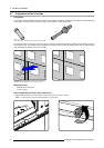
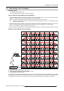
2. Complete the data path of the display by connecting all following tiles with data linking cables to each other in a daisy chain
manner. This daisy chain linking can be realized either in horizontal, which is recommended, or in vertical direction.
Note: Only one data port is used of the last tile in the data path.
3. Specify in the setup controlling software how the data path is realized (horizontal or vertical) and which tile is the first in the chain.
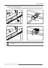
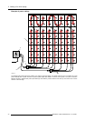
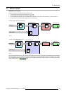
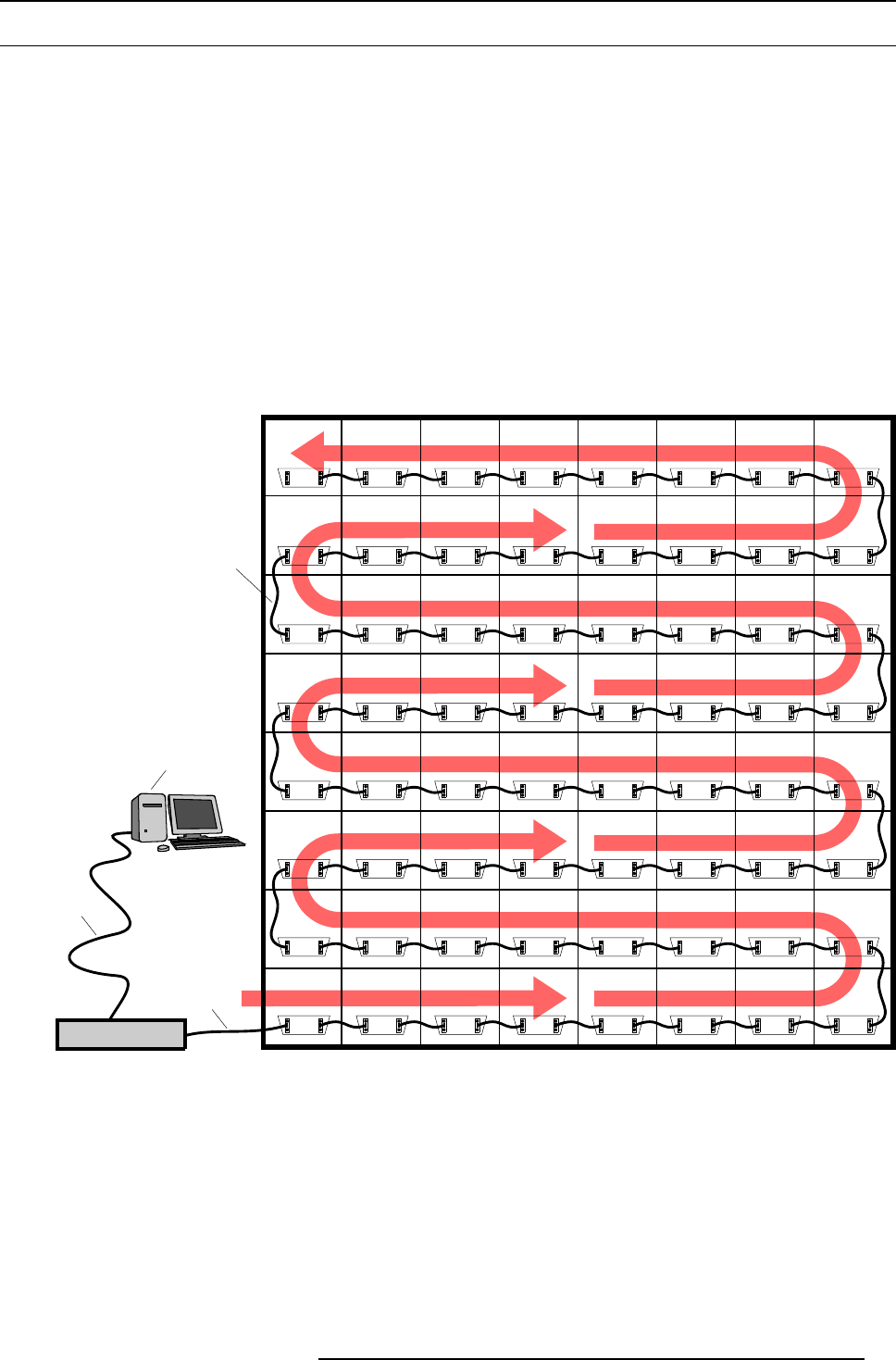
Example of data cabling of an ILite display
DIGITIZER
A
B
C
D
Image 5-4
A Local PC with control software.
B RS232 connection cable between
PC and digitizer.
C Data cable between digitizer and first tile (maximum 5 meter).
D Short data linking cable between tiles.
The example above shows the data cabling, seen from the rear, of an ILite display of eight tiles wide and eight tiles high. The data
path is realized in horizontal direction and starts in the lower left corner, seen from the rear. The settings in the control software refer
to the display seen from the front. So, the first tile in the data path has to be indicated as the lower right tile of the display.
R5976522 FIXED ILITE DISPLAY 17/11/2006
41