


2-4
Cisco AS5350 Universal Gateway Chassis Installation Guide
78-10754-03 0A
Chapter 2 Preparing to Install the CiscoAS5350 Chassis
Preparing to Connect to a Network
Warning
The ISDN connection is regarded as a source of voltage that should be inaccessible to user contact.
Do not attempt to tamper with or open any public telephone operator (PTO)-provided equipment or
connection hardware. Any hardwired connection (other than by a nonremovable,
connect-one-time-only plug) must be made only by PTO staff or suitably trained engineers. To see
translations of the warnings that appear in the publication, refer to the Regulatory Compliance and
Safety Information document that accompanied this device.
Ethernet Connections
Two Fast Ethernet (FE) ports, RJ-45 ports, are located on the rear panel of the universal gateway: FE0
and FE1 (selectable). To configure the Ethernet ports, refer to the Cisco AS5350 and Cisco AS5400
Universal Gateway Software Configuration Guide. Both ports use unshielded twisted-pair (UTP) cable
and require Category 5 cable. The maximum segment distance is 328 feet (100 meters).
Note UTP cables look like the cables used for ordinary telephones; however, UTP cables meet certain
electrical standards that telephone cables do not. Cables are not included.
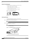
Console and Auxiliary Ports
The Cisco AS5350 includes an asynchronous serial console port and an auxiliary port. The console and
auxiliary ports provide access to the universal gateway either locally (with a console terminal) or
remotely (with a modem). This section discusses important cabling information to consider before
connecting a console terminal (an ASCII terminal or PC running terminal emulation software) to the
console port, or modem to the auxiliary port.
Console Port
The Cisco AS5350 includes an EIA/TIA-232 asynchronous serial console port (RJ-45). Depending on
the cable and the adapter used, this port will appear as a data terminal equipment (DTE) or data
communications equipment (DCE) device at the end of the cable. Your universal gateway arrives with
cables and adapters to connect a console terminal (an ASCII terminal or PC running terminal emulation
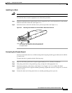
software) to the console port. To connect an ASCII terminal to the console port, use the RJ-45 rollover
cable with the female RJ-45-to-DB-25 adapter (labeled TERMINAL).
To connect a PC running terminal emulation software to the console port, use the RJ-45 rollover cable
with the female RJ-45-to-DB-9 adapter (labeled TERMINAL). The default parameters for the console
port are 9600 baud, 8 data bits, no parity, and 2 stop bits. The console port does not support hardware
flow control.
For detailed information about installing a console terminal, see Chapter 3, “Installing the
Cisco AS5350.” See Appendix C, “Cabling Specifications,” for cable and port pinouts.