


3-9
Cisco AS5350 Universal Gateway Chassis Installation Guide
78-10754-03 0A
Chapter 3 Installing the Cisco AS5350
Connecting to the Network
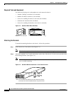
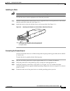
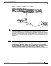
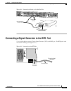
Figure 3-9 Connecting an 8-Port DFC to a RJ-45 (T1) Jack
Note Use software commands to choose a specific port and the line termination on that port. For information
on software commands, see the Cisco AS5350 and Cisco AS5400 Universal Gateway Software
Configuration Guide. This document is available on the Cisco.com and the documentation CD-ROM that
comes with your universal gateway. (See the “Obtaining Documentation” section on page xiii.) If you
choose a port with 75-ohm input impedance, use an RJ-45-to-75-ohm coaxial cable adapter and plug it
into that port.
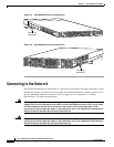
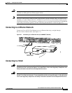
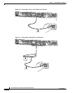
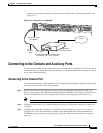
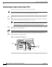
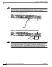
• Connect each E1/PRI port to an RJ-45 jack with a straight-through RJ-45 to RJ-45 cable. (See
Figure 3-10 and Figure 3-11.)
Warning
The E1 interface card may only be installed in an ACA-permitted customer equipment or a Data
Terminal Equipment (DTE) that is exempted from ACA’s permit requirements. The customer equipment
must only be housed in a cabinet that has screw-down lids to stop user access to overvoltages on the
customer equipment. The customer equipment has circuitry that may have telecommunications
network voltages on them. To see translations of the warnings that appear in the publication, refer to
the Regulatory Compliance and Safety Information document that accompanied this device.
56057
T1/E1 8 PRI
connector
RJ-45 jack
P
1
P
2
P
3
P
4
P
5
P
6
P
7
P
0
Straight-through
RJ-45-to-RJ-45 cable