


-1
Cisco AS5350 Universal Gateway Chassis Installation Guide
78-10754-03 0A
APPENDIX
C
Cabling Specifications
This appendix provides the following cabling and pinout information for the Cisco AS5350 universal
gateway:
• Console and Auxiliary Port Cables and Pinouts, page C-1
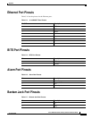
• Ethernet Port Pinouts, page C-5
• BITS Port Pinouts, page C-5
• Alarm Port Pinouts, page C-5
• Bantam Jack Port Pinouts, page C-5
Note This appendix provides cabling information for chassis connections only. For cabling information for
the Cisco AS5350 dial feature cards, see the Cisco AS5350 Universal Gateway Card Installation Guide.
Note This appendix specifies pinouts only for the pins used. Pins not listed in the tables in this appendix are
not connected.
Console and Auxiliary Port Cables and Pinouts
The universal gateway arrives with a console and auxiliary cable kit, which contains the cable and
adapters you need to connect a console (an ASCII terminal or PC running terminal emulation software)
or modem to your universal gateway. The console and auxiliary cable kit includes:
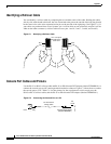
• RJ-45-to-RJ-45 rollover cable (See the next section, “Identifying a Rollover Cable,” for more
information).
• RJ-45-to-DB-9 female DTE adapter (labeled TERMINAL).
• RJ-45-to-DB-25 female DTE adapter (labeled TERMINAL).
• RJ-45-to-DB-25 male DCE adapter (labeled MODEM).
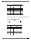
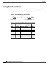
For console connections, proceed to the “Console Port Cables and Pinouts” section on page C-2. For
modem connections, proceed to the “Auxiliary Port Cables and Pinouts” section on page C-4.