


-13
Cisco AS5350 Universal Gateway Chassis Installation Guide
78-10754-03 0A
Appendix
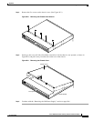
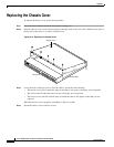
Replacing the Chassis Cover
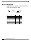
Step 5 If you installed a different type of power supply (AC or DC) than was originally installed in the
universal gateway, place one of the power ratings labels that came in the plastic bag with the
documentation directly over the power ratings information on the rear panel. For example, if the
original chassis came with an AC power supply and you replaced it with a DC power supply, place the
DC power ratings label over the ratings stamped on the rear panel of the chassis. This will ensure that
the correct power ratings information appears on the rear panel. (See Figure B-15 and Figure B-16.)
Step 6 Reinstall the chassis on a rack, desktop, or table.
Step 7 Reinstall all interface cables.
Step 8 Reconnect the AC power cord. Or, if you are using a DC-powered unit, refer to Figure B-17 or
Figure B-18, and complete the steps appropriate for each power supply.
Warning
The illustration shows the DC power supply terminal block. Wire the DC power supply using the
appropriate wire terminations at the wiring end, as illustrated. The proper wiring sequence is ground
to ground, return to return, and negative to negative. Note that the ground wire should always be
connected first and disconnected last. To see translations of the warnings that appear in this
publication, refer to the Regulatory Compliance and Safety Information document that accompanied
this device.
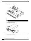
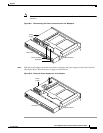
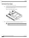
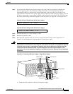
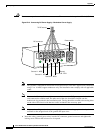
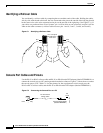
Figure B-17 Connecting DC Power Supply—Single Power Supply
a. Connect the DC connector to the rear of the power supply.
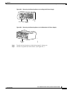
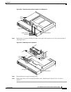
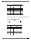
Figure B-15 Power Ratings Label for DC Power Supply
INPUT -48/-60V == 3A 150VA
Figure B-16 Power Ratings Label for AC Power Supply
INPUT 100 – 240V~ 50/60Hz 2 – 1A
56022
Power switch
Source A - NEG
Source A - RTN
Source B - NEG
Source B - RTN
Ground
To DC source
DC connector