


3-3
Cisco AS5350 Universal Gateway Chassis Installation Guide
78-10754-03 0A
Chapter 3 Installing the Cisco AS5350
Setting Up the Chassis
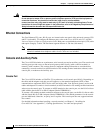
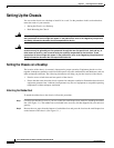
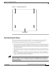
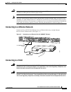
Figure 3-1 Attaching the Rubber Feet
Rack-Mounting the Chassis
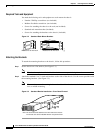
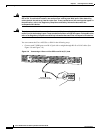
This section describes how to rack-mount the chassis. The universal gateway arrives with 19-inch
rack-mount brackets and larger brackets for use with a 23- or 24-inch rack (See Figure 3-2).
The following information will help you plan your equipment rack configuration:
• Enclosed racks must have adequate ventilation. Ensure that the rack is not congested, because each
unit generates heat. An enclosed rack should have louvered sides and a fan to provide cooling air.
Heat generated by equipment near the bottom of the rack can be drawn upward into the intake ports
of the equipment above.
• When mounting a chassis in an open rack, ensure that the rack frame does not block the intake or
exhaust ports. If the chassis is installed on slides, check the position of the chassis when it is seated
in the rack.
• Baffles can isolate exhaust air from intake air, which also helps to draw cooling air through the
chassis. The best placement of the baffles depends on the airflow patterns in the rack, which can be
found by experimenting with different configurations.
Warning
Before working on a chassis or working near power supplies, unplug the power cord on AC units;
disconnect the power at the circuit breaker on DC units. To see translations of the warnings that
appear in the publication, refer to the Regulatory Compliance and Safety Information document that
accompanied this device.
37208
Universal gateway
chassis bottom