


-14
Cisco AS5350 Universal Gateway Chassis Installation Guide
78-10754-03 0A
Appendix
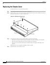
Replacing the Chassis Cover
Caution Do not overtorque the terminal block contact screws. The recommended torque is 4.5 lb-in (0.50 N-m).
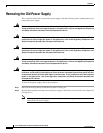
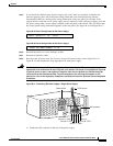
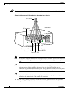
Figure B-18 Connecting DC Power Supply—Redundant Power Supply
Note This product is intended for installation in restricted access areas and is approved for connection
using 12 or 14 AWG copper conductors only. The installation must comply with all applicable
codes.
Note For central office installations, it is recommended to use a 6 AWG green ground wire with one
end connected to reliable earth. The other end of the wire should be crimped onto the
double-hole lug provided in the installation pack. The lug should be secured to the mating holes
on the side of the chassis with the two screws included in the accessory pack.
Note If you are installing a redundant power supply, you should attach appropriate sized spade
terminals to the stripped ends of the ground and input wires.
a. Insert the safety ground (green wires) into the DC connector ground connector and tighten the
locking screw. Ensure that no bare wire is exposed.
A- A+
B- B+
82637
Power switch
Source A - NEG
Source A - RTN
Source B - NEG
Source B - RTN
Ground
To DC source
DC connector