


-3
Cisco AS5350 Universal Gateway Chassis Installation Guide
78-10754-03 0A
Appendix
Console and Auxiliary Port Cables and Pinouts
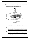
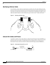
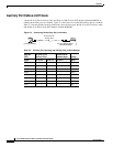
Use the RJ-45-to-RJ-45 rollover cable and RJ-45-to-DB-25 female DTE adapter (labeled TERMINAL)
to connect the console port to a terminal. Figure C-3 shows how to connect the console port to a terminal.
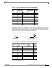
Table C-2 lists the pinouts for the asynchronous serial console port, the RJ-45-to-RJ-45 rollover cable,
and the RJ-45-to-DB-25 female DTE adapter (labeled TERMINAL).
Figure C-3 Connecting the Console Port to a Terminal
Table C-1 Console Port Signaling and Cabling Using a DB-9 Adapter
Console Port
(DTE)
RJ-45-to-RJ-45
Rollover Cable
RJ-45-to-DB-9
Terminal Adapter
Console
Device
Signal RJ-45 Pin RJ-45 Pin DB-9 Pin Signal
RTS 1
1
1. Pin 1 is connected internally to pin 8.
88 CTS
DTR 2 7 6 DSR
TxD 3 6 2 RxD
GND 4 5 5 GND
GND 5 4 5 GND
RxD 6 3 3 TxD
DSR 7 2 4 DTR
CTS 8
1
17 RTS
Table C-2 Console Port Signaling and Cabling Using a DB-25 Adapter
Console Port
(DTE)
1
1. You can use the same cabling to connect a console to the auxiliary port.
RJ-45-to-RJ-45 Rollover
Cable
RJ-45-to-DB-25
Terminal
Adapter
Console
Device
Signal RJ-45 Pin RJ-45 Pin DB-25 Pin Signal
RTS 1
2
2. Pin 1 is connected internally to pin 8.
85 CTS
DTR 2 7 6 DSR
TxD 3 6 3 RxD
GND 4 5 7 GND
GND 5 4 7 GND
RxD 6 3 2 TxD
DSR 7 2 20 DTR
CTS 8
1
14 RTS
Terminal
RJ-45-to-RJ-45
rollover cable
RJ-45-to-DB-25 adapter
(labeled TERMINAL)
37210
Universal gateway