


3-2
Cisco AS5350 Universal Gateway Chassis Installation Guide
78-10754-03 0A
Chapter 3 Installing the Cisco AS5350
Setting Up the Chassis
Setting Up the Chassis
You can set the chassis on a desktop or install it in a rack. Use the procedure in this section that best
meets the needs of your network:
• Setting the Chassis on a Desktop
• Rack-Mounting the Chassis
Warning
When installing the unit, the ground connection must always be made first and disconnected last. To
see translations of the warnings that appear in the publication, refer to the Regulatory Compliance
and Safety Information document that accompanied this device.
Warning
This unit is intended for installation in restricted access areas. A restricted access area is where
access can only be gained by service personnel through the use of a special tool, lock and key, or
other means of security, and is controlled by the authority responsible for the location. To see
translations of the warnings that appear in the publication, refer to the Regulatory Compliance and
Safety Information document that accompanied this device.
Setting the Chassis on a Desktop
The location of the chassis is extremely important for proper operation. Equipment placed too close
together, inadequate ventilation, and inaccessible panels can cause malfunctions and shutdowns, and can
make maintenance difficult. The following information will help you plan the location of the chassis:
• Plan for access to both front and rear panels of the chassis.
• Ensure that the room where the chassis operates has adequate ventilation. Remember that electrical
equipment generates heat. Ambient air temperature may not cool equipment to acceptable operating
temperatures without adequate ventilation.
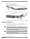
Attaching the Rubber Feet
To attach the rubber feet to the chassis, follow this procedure:
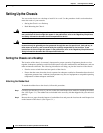
Step 1 Carefully turn the chassis over so you can see the four small depressions made for attaching the rubber
feet. (See Figure 3-1.) The rubber feet are included in the accessory kit that shipped with your universal
gateway.
Step 2 Remove the wax paper from the bottom of each rubber foot and press the foot into the small depression
on the bottom of the chassis. (See Figure 3-1.)