


3-18
Cisco AS5350 Universal Gateway Chassis Installation Guide
78-10754-03 0A
Chapter 3 Installing the Cisco AS5350
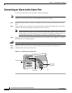
Supplying Power
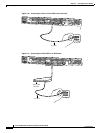
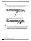
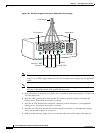
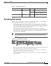
Figure 3-20 DC Power Supply Connections—Redundant Power Supply
Note This product is intended for installation in restricted access areas and is approved for connection
using 12 or 14 AWG copper conductors only. The installation must comply with all applicable
codes.
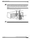
Note If you are installing a redundant power supply, you should attach appropriate sized spade
terminals to the stripped ends of the ground and input wires.
a. Strip off a quarter of an inch (1/4 in. [0.625 cm]) of insulation on the safety ground, +48 VDC, and
-48 VDC input wires.
b. Insert the safety ground (green wire) into the DC connector ground connector and tighten the
locking screws. Ensure that no bare wire is exposed.
c. Insert the 48 VDC Return wires into the DC connector positive connectors (+) and tighten the
locking screws. Ensure that no bare wire is exposed.
d. Insert the -48 VDC wires into the DC connector negative connectors (-) and tighten the locking
screws. Ensure that no bare wire is exposed.
e. Make sure that the power supply wires are secured to cable strain-relief clamps with cable ties.
A- A+
B- B+
82637
Power switch
Source A - NEG
Source A - RTN
Source B - NEG
Source B - RTN
Ground
To DC source
DC connector