


3-14
Cisco AS5350 Universal Gateway Chassis Installation Guide
78-10754-03 0A
Chapter 3 Installing the Cisco AS5350
Connecting an Alarm to the Alarm Port
Connecting an Alarm to the Alarm Port
To connect an alarm device to the alarm port, follow this procedure:
Note The alarm connector is a 3-wire connector that plugs into a receptacle in the rear of the chassis. The
connector is provided in the accessory kit that ships with the Cisco AS5350.
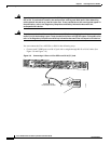
Step 1 Insert the three pin alarm port connector (included in the accessory kit) into the alarm port terminal
block.
Step 2 Strip a minimum 1/4 in. (0.625 cm) off the wire insulation to connect the stranded wires to the alarm
connector. The maximum insulation strip length is 0.31 in. (0.78 cm).
Note Connect the alarm port only to a safety extra-low voltage (SELV) source using 22 AWG, or
thicker, copper wire. SELV ratings are maximum 30 Volts AC (RMS), maximum 60 Volts DC,
and maximum 50 VA power. The alarm port is rated for 2.0 Amp maximum current.
Step 3 Secure the wires to the alarm connector with the screws on the connector. See Appendix C, “Cabling
Specifications,” for alarm port pinouts.
Caution The maximum tightening torque on the screws is 7 in.-lb (0.79 N-m).
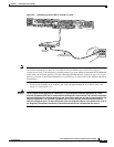
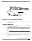
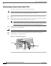
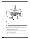
Step 4 Attach two cable ties to the chassis and connect the wires to the cable ties. (See Figure 3-16.)
Step 5 Attach the alarm wires to the alarm device.
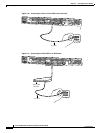
Figure 3-16 Connecting to the Alarm Port
35967
Alarm port
connector
To alarm device
Cable ties
#1
#2
#3