


4-3
Cisco AS5350 Universal Gateway Chassis Installation Guide
78-10754-03 0A
Chapter 4 Troubleshooting
Monitoring Environment
Monitoring Environment
The Cisco AS5350 contains temperature sensors to detect abnormal temperature conditions during
system operation. The three levels of sensor detection are as follows:
• If the operating temperature of the system exceeds 45° C, the system reaches a warning state. A
warning message appears on the console. When the operating temperature of the system drops below
45° C, another message is displayed on the console indicating a recovery. At this level of sensor
detection, there is no disruption in system operation.
• When the operating temperature of the system continues to rise above 45° C and reaches a
temperature of 60°C, the system reaches a critical state. Cisco IOS software gracefully shuts down
the first DFC. If the operating temperature continues to be critical after 10 minutes, Cisco IOS
software shuts down another DFC.
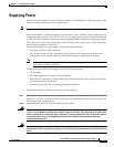
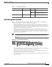
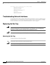
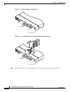
Note DFC slot numbering starts from the motherboard and works up from left to right. Slot 0 is
reserved for the motherboard. The DFC slots are numbered sequentially from 1 to 3. (See
Figure 4-2.)
Figure 4-2 Cisco AS5350 Slot Numbering
This process is repeated at 10 minute intervals until the final DFC is shut down. The console displays
the slot number of the DFC and the type of DFC that was shut down.
If the operating temperature cools down to 45°C, Cisco IOS software powers on the first DFC,
repeating the process for each DFC at 10 minute intervals.
• When the operating temperature of the system rises above 65° C, Cisco IOS software shuts down all
DFCs immediately.
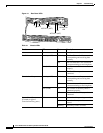
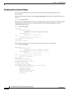
Serial Ports T0, T1 Flickering Indicates data activity on the serial
ports.
Off The serial port connection is not
transmitting or receiving data.
BITS Port BITS ON Indicates a valid signal on the BITS
port.
Table 4-1 Chassis LEDs (continued)
Function LED State Description
36006
Slot 2
Slot 0
Slot 1
Slot 3