


3-5
Cisco AS5350 Universal Gateway Chassis Installation Guide
78-10754-03 0A
Chapter 3 Installing the Cisco AS5350
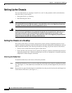
Setting Up the Chassis
Installing in a Rack
Caution Do not use the handles on the dial feature cards to assist in lifting the chassis.
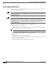
To install the chassis into the equipment rack, follow this procedure:
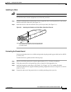
Step 1 With the mounting brackets attached to the chassis, support the chassis and align the holes in the brackets
with the screw holes in the rack. (See Figure 3-4.)
Step 2 Attach the chassis to the rack with the screws you have provided. (See Figure 3-4.)
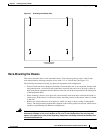
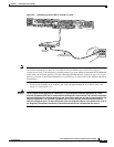
Figure 3-4 Attaching the Chassis to a 19-Inch Rack—Rear Panel Forward
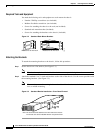
Connecting the Chassis Ground
You must connect the chassis to a reliable earth ground using the ground lug (provided) and size AWG 6
(13 mm2) wire.
To attach the chassis ground, take the following steps:
Step 1 Strip one end of the ground wire to expose approximately 0.75 in. (20 mm) of conductor.
Step 2 Crimp the ground wire to the ground lug, using a crimp tool of the appropriate size.
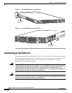
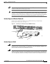
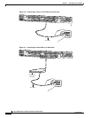
Step 3 Attach the ground lug to the chassis. (See Figure 3-5 or Figure 3-6.) Use a medium flat-blade
screwdriver and the screws supplied with the ground lug. Tighten the screws to a torque of 8 to 10 in-lb
(0.9 to 1.1 N-m).
Step 4 Connect the other end of the ground wire to a suitable grounding point at your site.
35659
Note: The second bracket attaches to the rack at the other side
of the chassis. The chassis can also be installed with the
front panel forward.