


-15
Cisco AS5350 Universal Gateway Chassis Installation Guide
78-10754-03 0A
Appendix
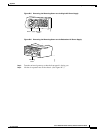
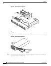
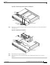
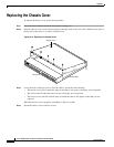
Replacing the Chassis Cover
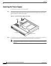
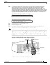
b. Insert the +48 VDC return wires into the DC connectors (+) and tighten the locking screws. Ensure
that no bare wire is exposed.
c. Insert the -48 VDC wires into the DC negative connectors (-) and tighten the locking screws. Ensure
that no bare wire is exposed.
d. Make sure that the power supply wires are secured to cable strain-relief clamps with cable ties.
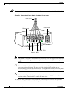
Warning
After wiring the DC power supply, remove the tape from the circuit breaker switch handle and
reinstate power by moving the handle of the circuit breaker to the ON position. To see translations of
the warnings that appear in this publication, refer to the Regulatory Compliance and Safety
Information document that accompanied this device.
Step 9 Power on the universal gateway.
The internal power supply fan should power on.