


-4
Cisco AS5350 Universal Gateway Chassis Installation Guide
78-10754-03 0A
Appendix
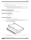
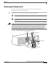
Removing the Chassis Cover
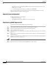
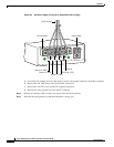
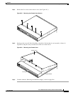
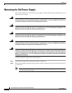
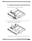
Figure B-2 DC Power Supply Connections—Redundant Power Supply
a.
Loosen the five locking screws for the negative, return, and ground connectors on the DC connector.
b. Remove the +48 VDC return wires from the DC connectors.
c. Remove the -48 VDC wires into the DC negative connectors.
d. Remove the safety ground wire from the DC connector.
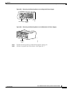
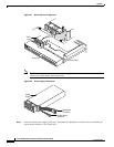
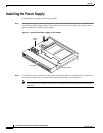
Step 2 Remove all interface cables from the rear panel of the universal gateway.
Step 3 Place the universal gateway so that the front panel is facing you.
A- A+ B- B+
82637
Power switch
Source A - NEG
Source A - RTN
Source B - NEG
Source B - RTN
Ground
To DC source
DC connector