


dCS 904 User Manual Manual for Software Version 1.5x and 1.36
dCS Ltd June 2000
Manual part no: DOC135904 iss 2B2
Page 13
135904ma2b2.pdf file available from website
Contact
dCS
on + 44 1799 531 999 email to: more@dcsltd.co.uk
(inside the UK replace + 44 with 0) web site: www.dcsltd.co.uk
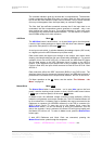
Pressing the Word Length button repeatedly cycles the word length through the
sequence:
24, 23, 22, 21, 20, 19, 18, 17, 16, 24, etc.
The Word Length is briefly shown on the main display, and if a setting other than
the maximum is set, the word length LED (above the button) lights.
Noise Shaping is a technique which improves the noise performance of the ADC
in the audio band by moving the quantisation noise energy (introduced by
reducing the word length) from one part of the spectrum to another. It keeps it
out of the middle of the band, where the ear is most sensitive, and places it at
the top end or ultrasonic region, where the ear is less sensitive or insensitive.
See section “Word Length Reduction” on page 64 for more background.
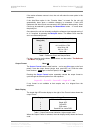
Pressing the Noise Shaping button repeatedly cycles the unit through 5 noise
Shaping characteristics. The characteristic is shown briefly on the main display.
Auto Unit sets noise shaping automatically, depending
on word length:
24 bits – no noise shaping
20 to 23 bits – 1
st
order noise shaping
16 to 19 bits – 3
rd
order noise shaping
Off No noise shaping
1st 1
st
order noise shaping
3rd 3
rd
order noise shaping
9th 9
th
order noise shaping
The noise shaping LED (above the button) lights when the setting is other
than Auto.
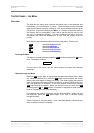
For Menu operation as the
Back button, see the section “The Software –
the Menu” on page 18.
Overload Level Menu
Step
The Overload Level button is dual function – on its own (blue type on the front
panel) it sets the level at which overloads are detected by the unit. With the
other menu buttons (
white type on the front panel) it is the menu Step button.
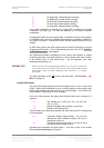
Overload detection is normally set to full scale. The detection level may be
reduced in 0.1dB steps down to -3dB0 by pressing the Overload Level button
repeatedly or holding it down. The set level is shown on the display for a few
seconds. The overload level LED (above the button) lights when the setting is
other than full scale (0.0dB0).
For Menu operation as the
Step button, see the section “The Software – the
Menu” on page 18.
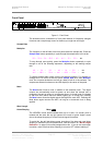
Overload Indicator (Overload LED)
This overload LED lights for a few seconds when the set overload level is
exceeded by a signal peak. The detection circuitry monitors both input and
digital filtering circuitry for overload conditions. The analogue input sensitivity
trims mounted on the rear panel should be set so that the overload indicator
does not light on signal peaks.