


dCS 904 User Manual Manual for Software Version 1.5x and 1.36
dCS Ltd June 2000
Manual part no: DOC135904 iss 2B2
Page 31
135904ma2b2.pdf file available from website
Contact
dCS
on + 44 1799 531 999 email to: more@dcsltd.co.uk
(inside the UK replace + 44 with 0) web site: www.dcsltd.co.uk
Clocking
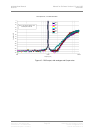
The sample clock quality significantly determines the output performance of an
ADC.
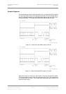
The highest quality clocks that are available are crystals, so we use these. In
Master mode, the dCS 904 uses one of two on-board voltage controlled crystal
oscillators (VCXOs) as clock sources – one for 48 kS/s related outputs and one
for 44.1 kS/s related outputs. When an external clock is applied for Slave
operation, the internal VCXO is synchronised to this by a phase locked loop
(PLL). The PLL is of a special narrow bandwidth type, that provides a high
degree of "clock cleaning" - but even so, signal quality may degrade if
particularly poor slave clocks are used. A consequence of the narrow bandwidth
is that it takes quite a long time for the PLL to lock to a new clock frequency – of
the order of 2 seconds. The PLL uses DSP assistance to keep this time
acceptable.
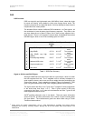
Internal clock -
Accuracy when shipped ± 10 ppm
Long Term Stability ± 10 ppm/year at room temp.
Temperature Stability ± 15 ppm over operating temperature range
The VCXO frequency can be trimmed by using the Offst function in the menu
(see page 23)– each VCXO is independently adjustable
Synchronising to source -
Pull in range ± 300 ppm about nominal frequency
Lock in time <2 seconds for most situations
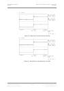
The PLL is very robust, and will lock to very poor signals if necessary. Data is
decoded using a much wider band (faster) PLL, so AES3 type low frequency
jitter on the input clock can be handled, and will be cleaned.
If you need to synchronise several items of digital equipment, we recommend
using a dCS 992 Master Clock.