


dCS 904 User Manual Manual for Software Version 1.5x and 1.36
dCS Ltd June 2000
Manual part no: DOC135904 iss 2B2
Page 84
135904ma2b2.pdf file available from website
Contact
dCS
on + 44 1799 531 999 email to: more@dcsltd.co.uk
(inside the UK replace + 44 with 0) web site: www.dcsltd.co.uk
Figures
Figure 1– Rear Panel..........................................................................................10
Figure 2 – Front Panel........................................................................................12
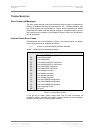
Figure 3 – Menu Sequence ................................................................................19
Figure 4 – DSD output configuration ..................................................................24
Figure 5 – Syncing a dCS 904 to a Master Clock ................................................24
Figure 6 – Storing 2 channel DSD on an 8 track 16 bit 44.1 kS/s PCM
recorder..........................................................................................25
Figure 7 – Six channel set up without a Master Clock........................................25
Figure 8 – Six channel DSD recording on a 24 track 16/44.1 kS/s recorder......26
Figure 9 – Multi-unit Remote Daisy Chain..........................................................27
Figure 10 – 8 Channel P3D DSD Set Up............................................................28
Figure 11 – DSD, showing DSD full scale ..........................................................34
Figure 12 – DSD Output, Filter Responses (Spot Q Noise) ...............................34
Figure 13 – DSD output, Filter responses (Integrated Q Noise).........................35
Figure 14 – DSD output, Filter responses (F weighted Spot Q Noise)...............35
Figure 15 – DSD output, with analogue and Q spot noise..................................36
Figure 16 – Word Clock and AES3 outputs, 96 kS/s..........................................37
Figure 17 – Word Clock and AES3 outputs, 44.1 kS/s.......................................37
Figure 18 – Word Clock in to Word Clock out, 96 kS/s......................................38
Figure 19 – Word Clock in to Word Clock out, 44.1 kS/s...................................38
Figure 20 – AES3 in to AES3 out, 96 kS/s .........................................................39
Figure 21 – AES3 in to AES3 out, 44.1 kS/s ......................................................39
Figure 22 – Word Clock in to AES3 out, 96 kS/s................................................40
Figure 23 – Word Clock in to AES3 out, 44.1 kS/s.............................................40
Figure 24 – 1
st
Order Noise Shapers implemented on dCS 904..........................42
Figure 25 – 3
rd
Order Noise Shapers implemented on dCS 904 .........................42
Figure 26 – 9
th
Order Noise Shapers implemented on dCS 904 .........................43
Figure 27 – AES3 format at 48 kS/s over 16 metres..........................................48
Figure 28 – AES3 format at 48 kS/s over 94 metres..........................................48
Figure 29 – AES3 format at 96 kS/s over 16 metres..........................................49
Figure 30 – AES3 format at 96 kS/s over 94 metres..........................................49
Figure 31 – SDIF-2 PCM format at 96 kS/s........................................................50
Figure 32 – SDIF-2 PCM format at 44.1 kS/s.....................................................51
Figure 33 – DSD using SDIF-2 electrical format ................................................52
Figure 34 – Temperature rise above ambient for a unit in a stack of 3 with
poor ventilation...............................................................................63
Figure 35 – Noise Shaping and Dither Spectra ..................................................66
Figure 36 – Truncation Only Spectra..................................................................67
Figure 37 – Changing Mains Fuse......................................................................70