


dCS 904 User Manual Manual for Software Version 1.5x and 1.36
dCS Ltd June 2000
Manual part no: DOC135904 iss 2B2
Page 61
135904ma2b2.pdf file available from website
Contact
dCS
on + 44 1799 531 999 email to: more@dcsltd.co.uk
(inside the UK replace + 44 with 0) web site: www.dcsltd.co.uk
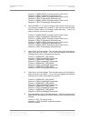
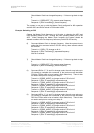
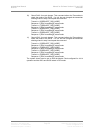
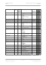
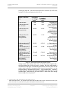
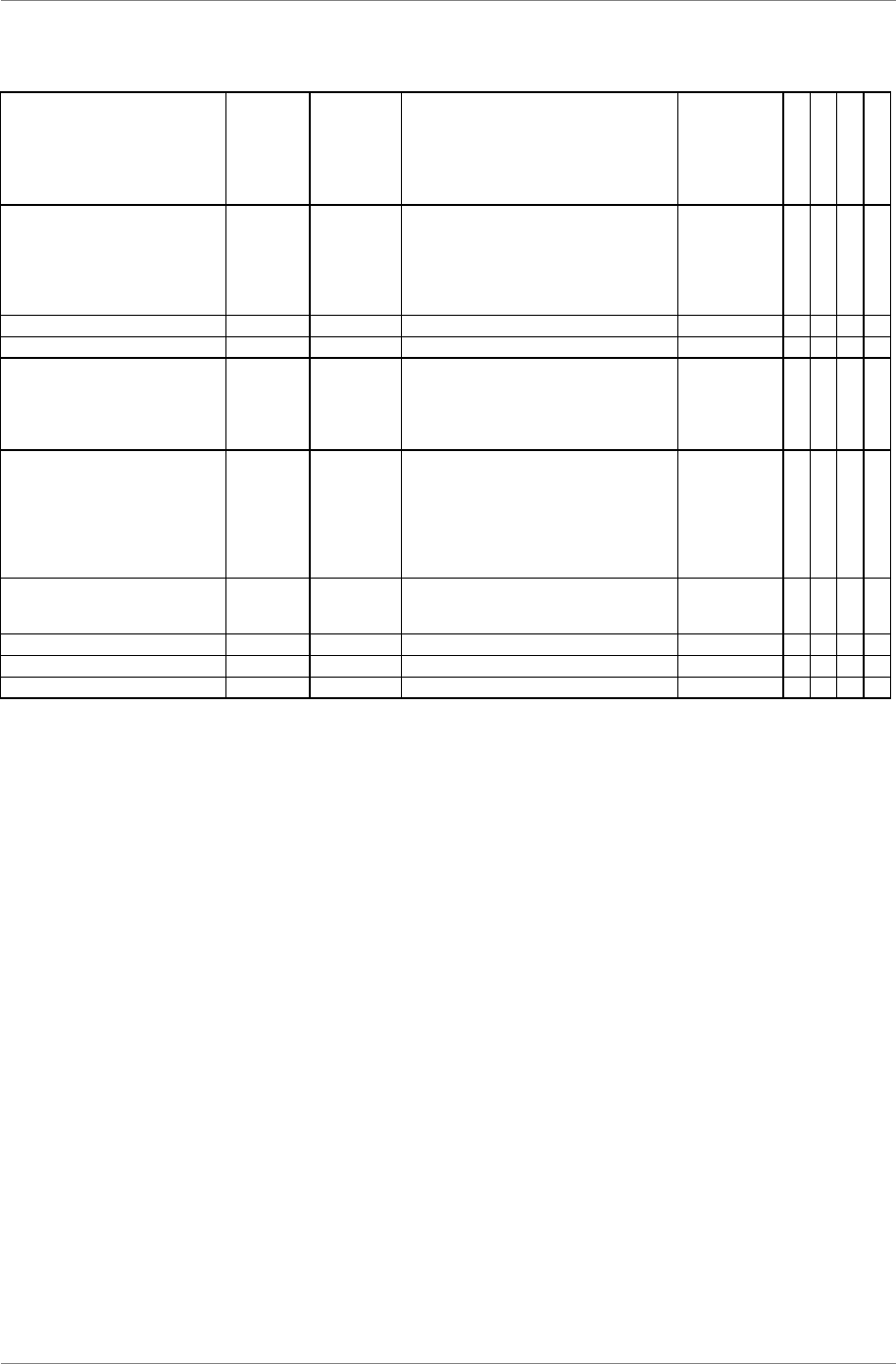
Command name Command
Byte
Number of
Parameters
in
Command
Parameters Parameters
in
Response
ADC
DAC
DDC
MClk
RS_REF_MODES
77 2 first parameter is terminator (AES)
0 = unterminated
1 = terminated
second is reference mode
1 = ref out is internal
0 = pass through
0XXX
RS_OVLD_LEV
87 1 Overload threshold, format X 0 X
RS_VOL
111 1 Digital volume control, format X 0 X X
RS_PHASE
112 1 Phase:
0 = None inverted
1 = Both inverted
2 = left inverted
3 = right inverted
0XX
RS_REF_MODE
114 1 Select reference input to clock from:
0 = AES1
1 = AES2
2 = SDIF-2 Clock (word clock)
3 = SPDIF1 or AES3
4 = SPDIF2 or AES4
5 = SPDIF3
0XX
RS_DSD_MODE
119 1 0 = DSD Off
1 = DSD (SDIF)
2 = 4-wire DSD
Echos
message
XXX
RS_BAUD_RATE
141 1 Global command None XXXX
REQUEST_DSD_MODE
142 0 response -> DSD mode Yes
REQUEST_FREQUENCY
143 0 response -> Frequency of unit Yes
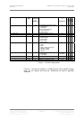
Table 11 – RS-232 Command Set
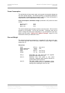
Format X – the level set number is –0.1dB times the 16 bit (positive integer)
used. So, for example, 260 would set –26dB below full scale for generator
amplitude.