


dCS 904 User Manual Manual for Software Version 1.5x and 1.36
dCS Ltd June 2000
Manual part no: DOC135904 iss 2B2
Page 14
135904ma2b2.pdf file available from website
Contact
dCS
on + 44 1799 531 999 email to: more@dcsltd.co.uk
(inside the UK replace + 44 with 0) web site: www.dcsltd.co.uk
The overload indication given by the dCS 904 is comprehensive. The detection
circuitry monitoring the digital filter does not simply check the final output word
but all the data from which the output word is formed. If any of these overload
(this may not be apparent from the output data), an overload is flagged.
The filter itself has sufficient numerical accuracy that if the input data is not
overloaded, the filter computations cannot generate an overload - only a raw
data overload can cause an error. The overload indication is thus much more
accurate than any external meter based indication - for this reason it is stored in
the AES/EBU validity bit for later reference.
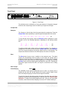
ADC/Data Menu
Set
The ADC/Data button is dual function – on its own (blue type on the front panel)
it sets the input mode (analogue or digital). With the other menu buttons (
white
type on the front panel) it is the menu
Set button.
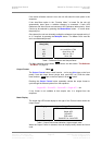
As an input mode switch, it switches between the analogue inputs (ADC mode)
or a digital input on the AES Reference input (Data mode).
Data mode routes the digital input through to the outputs, and makes noise
shaping, word length reduction and some reformatting available to it. For normal
operation, this is set to ADC (LED off). In Data mode, the ADC/Data LED lights
and the data stream on the AES Reference Input is output on the AES1-4
outputs. If the Reference Input sample rate is 88.2 or 96kS/s and the Output
Format is Dual AES, the input will be converted to Dual AES on AES1 & 2 and
AES3 & 4.
Data mode also affects the SDIF connectors (BNCs) in any DSD mode. The
data lines (two of the four connectors) become inputs, and DSD fed into these is
packed and re-formatted into the output format selected. No DSP is carried out.
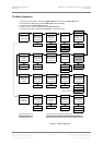
For Menu operation as the
Set button, see the section “The Software – the
Menu” on page 18.
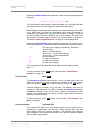
Master/Slave Menu
Down
The Master/Slave button is dual function – on its own (blue type on the front
panel) it sets the clocking mode (master or slave). With the other menu buttons
(
white type on the front panel) it is the menu Down button.
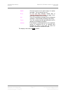
In Master mode, the calibrated voltage controlled crystal oscillators (VCXOs)
inside the unit generate an accurate sample rate. The LED labelled Master will
be lit to indicate this. If a Master Clock is available, this may be connected to the
Reference In connector (for AES/EBU reference) or the 75R In connector (for
SDIF-2 Word Clock). To slave the unit to the Master Clock, press the
Master/Slave button. The unit will attempt to lock to the Reference - this will
take a few seconds. If lock is achieved, the Slave LED will light up brightly and
the Master LED will turn off. To return to Master mode, press the Master/Slave
button again.
If both AES Reference and Word Clock are connected, pressing the
Master/Slave button cycles through the sequence:
Master ... AES Reference ... Word Clock ... Master ... etc.