


dCS 904 User Manual Manual for Software Version 1.5x and 1.36
dCS Ltd June 2000
Manual part no: DOC135904 iss 2B2
Page 64
135904ma2b2.pdf file available from website
Contact
dCS
on + 44 1799 531 999 email to: more@dcsltd.co.uk
(inside the UK replace + 44 with 0) web site: www.dcsltd.co.uk
G
ENERAL
T
ECHNICAL
I
NFORMATION
Word Length Reduction
Word length reduction (truncation) causes an error signal to be added to the
wanted signal. The error signal is usually referred to as “Q noise” or
Quantisation noise – the approximation is usually made that the errors are noise
like. This is reasonably true for large signals, where the errors are very complex
if they are not exactly noise like. Importantly, though, for smaller ones it is not
so. As the wanted signal gets smaller, the complexity of the error signal
decreases. The errors first of all pile into ever fewer lower order harmonics or
intermods, and then, as the level of the signal sinks below the Q level, the
majority of the error power piles into the signal fundamental. This causes its
amplitude to become unpredictable – it may drop abruptly to zero and
disappear, or it may cease to go down any more and just stay at a constant
level. From the audio viewpoint, this sounds very unpleasant. As a signal tail
decays away, the tonal quality changes, and then it decays into distorted mush
and then either abruptly stops, or else keeps fuzzing away until a new signal
starts. The level at which all this happens is the lsb of the output word – for
CDs, it is at the 16 bit level, which equates to about -90 dB0. The level is high
enough to be quite audible, and the effect must be tackled to make reasonable
quality end product.
There is really only one way of tackling the problem – another signal has to be
added to the wanted one to smooth the staircase transfer function that
truncation causes. Mathematically, with two signals present, the transfer function
that the wanted signal sees is the convolution of the PDF
10
of the second signal
and the staircase function. The converse is also true – the transfer function the
additional signal sees is the convolution of the PDF of the wanted signal and the
staircase function. This aspect is not a problem with the dither types considered
below, but it can be with some highly frequency shaped dithers.
The trick is to make the second signal as inaudible as possible. It is usually
referred to as dither, and it is usually noise like, because then its statistics can
be controlled, and the converse effect of the signal modulating the dither can be
made insignificant, or zero. However, there are a number of ways that this
dither signal can be generated and treated. The major options are:
• generate it from the signal or generate it independently and add it
(“Dither”). It seems implausible that the dither signal can be generated
from the signal, but it can, and this gives the lowest added noise power
option. It is noise shaping on its own, but there are some circumstances
where it needs help from additional dither.
• add inside or outside an error shaping loop
• frequency shape to match the ears response or not. One can use
techniques that suppress error energy in the areas where the ear is
sensitive, and put it in areas where the ear is not sensitive. Usually this
shuffling around process costs something – we remove a little from the
sensitive areas and add back rather more in the less sensitive parts, but
that’s life. We still gain some improvements.
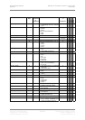
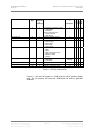
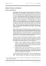
The table below gives the actual noise levels for 16 bit truncated signals with no
dither, various types of dither, noise shaping on its own, and noise shaping with
dither. The 0 dB reference level is taken as the minimum noise we could
10
PDF = Probability Distribution Function. References to Rectangular Dither or Triangular Dither refer the
shape of the PDF of the dither.