


dCS 904 User Manual Manual for Software Version 1.5x and 1.36
dCS Ltd June 2000
Manual part no: DOC135904 iss 2B2
Page 16
135904ma2b2.pdf file available from website
Contact
dCS
on + 44 1799 531 999 email to: more@dcsltd.co.uk
(inside the UK replace + 44 with 0) web site: www.dcsltd.co.uk
A1 for Single AES, Standard speed encoding
b1 for Single AES, Double speed encoding
b2 for Dual AES, Standard speed encoding
C2 for Dual AES, Double speed encoding
C4 for Quad AES, Standard speed encoding
If an invalid combination is selected (e.g. Single AES at 192kS/s), the invalid
combination will flash (e.g. C1) then be replaced by the nearest available
combination.
In Single AES mode, the same data stream is available on all four AES outputs.
In Dual AES mode, two sets of identical data streams are available on AES1 & 2
and AES3 & 4 outputs. In Quad AES mode, the data stream uses all four AES
outputs.
In DSD mode, data in the AES outputs can be turned off (leaving the unit just
outputting an AES clock). This is controlled by the menu item DSD 4
(or AES O
for P3D optioned units). See page 20.
dCS equipment encodes messaging into the various data streams to enable
receiving equipment to tell what is going on, and to decide which wire is which,
in the unlikely event of user wiring errors. Not all equipment from other
manufacturers does this, so:
IMPORTANT!
Take extra care when connecting Quad AES as it is very easy to connect the
wires in the wrong order. If this is not detected, it may result in badly aliased
mono signals being recorded. Numbering each connector is a sensible
precaution.
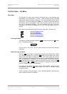
For Menu operation as the
Up button, see the section “The Software – the
Menu” on page 18.
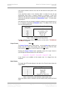
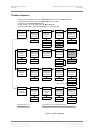
Sample Rate Display -
The main LED display generally shows the sample rate, in kS/s, or the mode
(DSD). When other parameters are set, it briefly shows the new setting (word
length, noise shaping, etc) then reverts to its normal display. In the case of an
error condition, it will display an error message.
If the unit is being slaved, the display also indicates which input connector it is
slaved to.
xxx The sample rate, in kS/s (32, 44.1, 48, 88.2, 86,
176.4, or 192).
- xxx Slaved to the BNC input (typically, word clock).
--
xxx Slaved to AES Reference in.
There are also some temporary displays that show what the unit is doing during
its locking phase:
d xxx Temporary display during locking – the unit has
detected the base reference sample rate and is
attempting to lock to it.
. xxx Temporary display during locking – the unit is lining
up word clock out to word clock in.
Important error messages are given below – a full list is given in the section
Error Codes and Messages on page 74.