


dCS 904 User Manual Manual for Software Version 1.5x and 1.36
dCS Ltd June 2000
Manual part no: DOC135904 iss 2B2
Page 33
135904ma2b2.pdf file available from website
Contact
dCS
on + 44 1799 531 999 email to: more@dcsltd.co.uk
(inside the UK replace + 44 with 0) web site: www.dcsltd.co.uk
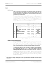
Filter Comments SQNR
(20 kHz,
dB)
SQNR
(
F weighted
dB)
E2 spec
(dB)
E3 spec
(dB)
1
High SQNR,
high stability
126.14 -136.56 -25.98 -28.96
2
High SQNR 127.23 -138.76 -25.85 -28.95
3
High SQNR,
very high
stability
124.66 -134.38 -27.32 -30.49
4
Extremely high
stability
122.07 -129.91 -25.54 -29.53
5
Reduced 100k
noise
122.27 -130.14 -27.13 -31.99
6
Single
complex zero
110.78 -151.02 -25.19 -23.55
7
Real zeros 101.5 -132.41 -25.29 -27.04
SACD Spec -20.00 -28.00
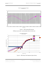
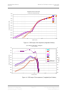
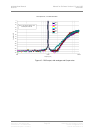
Table 4 – DSD Filter Performance
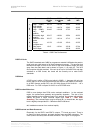
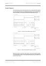
DSD Full Scale -
The SACD standard sets 0 dB0 for programme material 6 dB below the peak to
peak level one might expect a full scale sinewave to occupy. This ensures that
artefacts that begin to occur at the limits of the DSD frequency range stay well
away from the audio band, and is shown in Figure 11, on page 34. The dCS
904 complies with this standard. If the unit is set up for full scale PCM, and then
switched to a DSD format, the levels will be correctly set to meet SACD
standards.
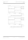
DSD Mute -
A DSD mute is unlike a PCM mute (which is 00000….), because with only two
levels, there is not a single value that sets the output in the middle of the range.
In all DSD formats except P3D, the dCS 904 outputs 010101010101…. as a
DSD mute. For P3D it outputs 01101001 as a P3D DSD mute.
DSD Overload Behaviour -
DSD is more benign than PCM under overload conditions. In the overload
region, the performance gradually and gracefully degrades. The size of this
region depends on the modulator used, but in general, a modulator with a higher
stability will allow a larger overload region (see Table 3 – DSD Filter
Summary). The overload region may be several dB. In the dCS 904, the signal
level is digitally clamped about 1.5 dB above SACD 0dB level.
dCS modulators recover from overload rapidly
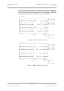
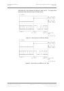
DSD Electrical and Data Structures -
Electrically, for the SDIF-2 and SDIF-3 outputs, TTL levels are used. There is
no framing or block structure, and each channel uses one BNC connector. The
clock (word or bit clock) uses the third connector. See Figure 33 on page 52.