


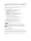
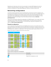

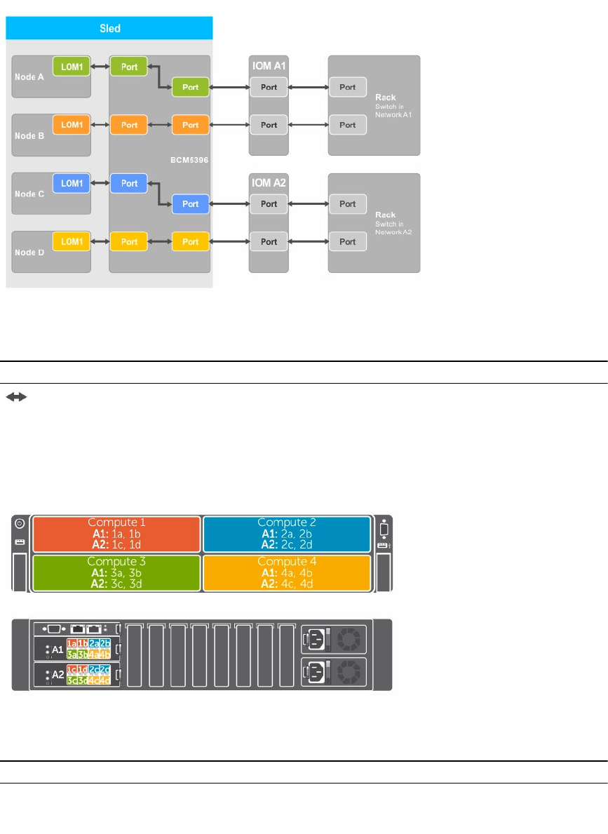
Figure 8. Enhanced network adapter isolation configuration
Table 8. Enhanced network adapter isolation configuration icon description
Icon Description
Network path
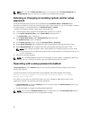
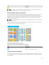
Node to I/O module port mapping for the enhanced network isolation configuration
In this configuration, each of the four nodes on an FM120x4 system is mapped to a single port on the I/O
module. The network traffic from the nodes in the compute sled to the I/O modules in the enclosure is
routed through a network switch that is embedded on the compute sled system board.
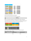
Figure 9. Node to I/O module port mapping for the enhanced network isolation configuration
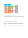
Table 9. I/O module port mapping — FM120x4
FM120x4 IO Module A1 (Top) IO Module A2 (Bottom)
1 1a, 1b 1c, 1d
2 2a, 2b 2c, 2d
31