


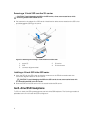
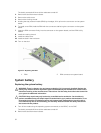
e. hard-drive/SSD backplane
f. hard drives/SSDs
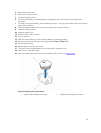
7. Remove the I/O connector cover from the back of the sled.
8. Install the sled in the enclosure.
9. Turn on the sled.
If BIOS detects a new system board and the service tag in the ERM, BIOS displays the service tag, the
status of the license, and the UEFI Diagnostics version for each node in the sled.
NOTE: Follow steps 10 and 11 to restore ERM information for each node in the sled.
10. Press any of the following keys for restore options for each node:
a. Y — to restore the service tag, license, and diagnostics information of each node.
b. N — to navigate to the Lifecycle Controller based restore options.
c. F10 — to restore data from a previously created Hardware Server Profile.
After the restore process is complete, BIOS prompts to restore the configuration data for each node.
11. Press the following keys to restore configuration data for each node:
a. Y — to restore the configuration data.
b. N — to use the default configuration settings.
After the restore process is complete, the system restarts.
Control panel
Removing the control panel
CAUTION: Many repairs may only be done by a certified service technician. You should only
perform troubleshooting and simple repairs as authorized in your product documentation, or as
directed by the online or telephone service and support team. Damage due to servicing that is
not authorized by Dell is not covered by your warranty. Read and follow the safety instructions
that came with the product.
1. Turn off the nodes using the operating system commands, or the iDRAC, or the CMC.
The sled is powered off when all the nodes are turned off.
2. Remove the sled from the enclosure.
3. Remove the following:
a. hard drives/SSDs
b. memory modules
c. cable cover
d. cooling shroud
e. hard-drive/SSD backplane
f. system board
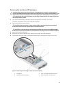
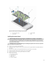
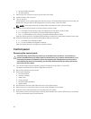
4. Disconnect the control-panel cable from the control-panel board.
5. Remove the two screws securing the control-panel assembly to the chassis.
6. Slide the control-panel assembly out and away from the chassis.
7. Remove the three screws securing the control-panel board to the control-panel bracket, and lift the
control-panel board away from the bracket.
56