


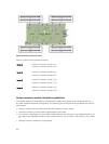
Sample memory configurations
The following table shows sample memory configurations that follow the appropriate memory guidelines
stated in this section.
NOTE: 1R and 2R in the following table indicate single- and dual-rank UDIMMs respectively.
Table 11. Memory configurations
Sled Capacity
(in GB)
DIMM Size
(in GB)
Number of
DIMMs
Organization and
Speed
DIMM Slot Population
16 4 4
1R x8, 1600 MT/s
A_A1, B_A1, C_A1, D_A1
24 4 6
1R x8, 1600 MT/s
A_A1, A_A2, B_A1, B_A2, C_A1, D_A1
32 4 8
1R x8, 1600 MT/s
A_A1, A_A2, B_A1, B_A2, C_A1,
C_A2, D_A1, D_A2
32 8 4
2R x8, 1600 MT/s
A_A1, B_A1, C_A1, D_A1
48 8 6
2R x8, 1600 MT/s
A_A1, A_A2, B_A1, B_A2, C_A1, D_A1
64 8 8
2R x8, 1600 MT/s
A_A1, A_A2, B_A1, B_A2, C_A1,
C_A2, D_A1, D_A2
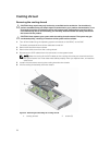
Removing memory modules
WARNING: The memory modules are hot to touch for some time after the system has been
powered down. Allow the memory modules to cool before handling them. Handle the memory
modules by the card edges and avoid touching the components or metallic contacts on the
memory module.
CAUTION: Many repairs may only be done by a certified service technician. You should only
perform troubleshooting and simple repairs as authorized in your product documentation, or as
directed by the online or telephone service and support team. Damage due to servicing that is
not authorized by Dell is not covered by your warranty. Read and follow the safety instructions
that came with the product.
1. Turn off the nodes using the operating system commands, or the iDRAC, or the CMC.
The sled is powered off when all the nodes are turned off.
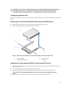
2. Remove the sled from the enclosure.
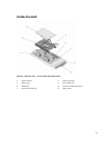
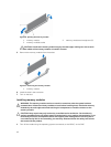
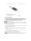
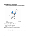
3. Locate the appropriate memory module socket(s).
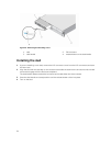
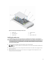
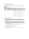
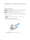
4. To release the memory-module from the socket, simultaneously press the ejectors on both ends of
the memory module socket.
41