


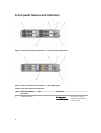
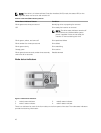
Item Indicator, Button, or
Connector
Icon Description
1.8 inch SSD
system
Eight 1.8 inch hot-
swap SATA SSDs.
2 Sled power-on
indicator, power
button
The power-on indicator lights when the sled
power is on. The power button controls the
power supply output to the system.
3 Node status indicators Provide information about the status of the
four nodes in the sled.
4 USB select button Allows you to assign the USB port to a
particular node in the sled.
5 USB connector Allows a USB device to be connected to the
system.
6 Sled handle Used to slide the sled out of the enclosure.
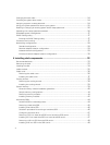
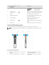
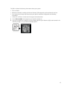
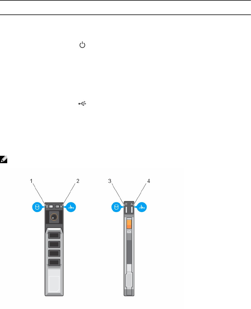
Hard-drive/SSD indicator patterns
The hard-drive/SSD indicators display different patterns as drive events occur in the system.
NOTE: The sled must have a hard drive/SSD or a hard-drive/SSD blank installed in each drive bay.
Figure 3. Hard-drive/SSD indicators
1. drive activity indicator (green) — 2.5 inch hard
drive/SSD
2. drive status indicator (green and amber) —
2.5 inch hard drive/SSD
3. drive activity indicator (green) — 1.8 inch SSD 4. drive status indicator (green and amber) —
1.8 inch SSD
9