


58 59
CHAPTER 8 HARD DISK DRIVE
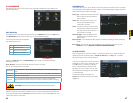
Anti-dither – This is the hold time you want the system to delay before beginning recording on
an alarm.
Latch Time – This is the time that the DVR will before starting a new event (10 seconds to 300
seconds (5 minutes)) after the alarm is ended.
Alarm Out – This will send an alarm signal to up to three connected external alarms when
enabled.
Show Message – When this is enabled, an alert message will be displayed on the DVR’s
screen.
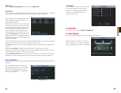
Alarm Out – To utilize this feature you must connect have at least one external alarm attached
to the DVR. You may have up to three separate alarms.
Show Message – When this is enabled, the system will bring up the Alarm Status window
whenever an event is detected. You can configure this to display when motion, video
loss or masking is detected.
Alarm Upload – The system can upload the alarm to the network including to an alarm
monitoring service.
Send E-mail – E-mail notifications can be sent a single e-mail address. Please see the
Section 1.2 Advanced Network Setup in the Remote Monitoring Guide for
instructions on how to set up the e-mail alerts including recipient address.
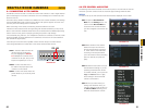
Record Channel – When one camera detects an event, you can set the DVR to activate
recording on other cameras.
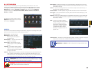
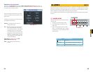
PICTURE 7-5
PTZ Activation – If you have Pan-Tilt-Zoom
cameras connected to the DVR, you
can cause them to be activated when
an alarm occurs. You can further
instruct it to perform one of 255 pre-
set activities. You can also allow a
delay of 0 to 300 seconds before
the PTZ camera(s) activates. Setting
up these pre-programmed functions
is covered in Section 6.2 PTZ
Control and Setup.
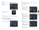
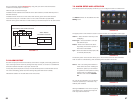
Tour - When enabled, this causes the DVR’s display to cycle through selected Live View
channels while maintaining the selected recording functions. Instructions for
configuring this feature are found in Section 5.3 Setting Menu.
Snapshot - When this is selected, the DVR will begin recording still images, in addition
to whatever video is being recorded, and it will upload or e-mail these images as
configured in Section 5.3 Setting Menu.
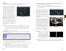
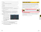
HARD DISK DRIVE
CHAPTER 8
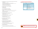
Your DVR uses a standard laptop computer 2.5-inch SATA (Serial Advanced Technology
Attachment) hard disk drive and has been tested with up to a 500GB drive. These drives
are the current industry standard and may be purchased wherever computer parts are sold.
Depending on where you purchased your DVR, it may come with a pre-installed drive. But,
we recognize that you may wish to upgrade or replace your drive in the future so this DVR is
designed to make installation and replacement easy for the average user.
It should be noted that while this is the only user-serviceable part within the case and you will
not void your warranty by installing or upgrading your hard disk drive, care must be taken to
avoid damage to the other components within the case.
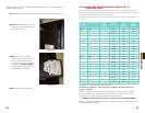
8.1 INSTALLATION/REMOVAL
It is strongly advised against opening the case when atmospheric conditions present the risk
of static discharge which can damage electronic components. It is also recommended that
you place the DVR face-down on a static-free, non-scratch surface to avoid damage to the
screen or finish of the case.
Complete installation instructions are on the next page.
WARNING! ELECTRIC SHOCK RISK!
The DVR MUST be unplugged from all power sources as well
as from the cameras before opening the case. Failure to do so
can result in damage to the DVR or its components as well as
injury or death.