


10 11
Please note that it is important to keep in mind common safety guidelines when installing your
DVR or connecting additional devices – including turning off and unplugging your DVR before
installing internal components.
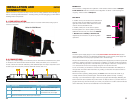
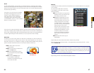
2.1 DVR INSTALLATION
This DVR can be mounted on the included stand or it can be wall-mounted using a pair of
screws (not included).
INSTALLATION AND
CONNECTION
CHAPTER 2
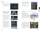
2.2 CONNECTIONS
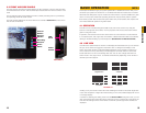
As part of its compact design, the connection ports on this DVR are concentrated on a panel
on the back of the device located above the stand. These ports allow you to connect the
mouse, cameras and network cable along with additional input and output components such
as alarms, pan-tilt-zoom (PTZ) cameras, additional monitors and so on.
Power
The DVR’s power supply plugs into the socket (Item number 3 in Picture 2-2) located
on the underside of the unit. It is absolutely essential that you only use the power supply that
came with the DVR to ensure proper operation and to avoid damage.
We also recommend that you use an uninterrupted power supply (UPS) so that the system will
continue to operate in the event of a power loss. In addition, you should connect the DVR into
a UL-1449 rated surge protector. It should have a joule rating of at least 400, a response time
of 10 nanoseconds or less and a clamping voltage of no more than 330 volts.
To turn on the DVR, you will need to use the Power button located below the USB ports on
the right side of the DVR. When the DVR is off, pushing on the button will cause the DVR to
initialize and power up.
When the DVR is operating, briefly pressing the Power button will cause the screen to go
to sleep until the button is pressed again. The DVR will still operate normally - including
recording. If you hold the button longer, a Shut Down progress bar will display. Releasing the
button before the bar completes will put the monitor to sleep as above. If you allow the bar to
progress all the way, the DVR will ask you to enter your password to confirm and then will shut
down. Afterwards, the DVR can be restarted in the normal fashion.
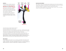
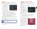
DC 12V
AUDIO/VIDEO/NET
1 2 3 4 NO C A B Rx Tx
1 2 3 4 5
Holes for Wall Mount
PICTURE 2-1
Item Description Item Description
1 Network Connection Indicator Light 2 Network Activity Status Light
3 DC Power Input 4 Audio, Video and Network
Connection Port (via dongle)
5 RS232 and RS485 Ports, Alarm Input and Output
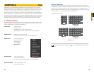
PICTURE 2-2
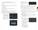
PICTURE 2-3
USB
Ports
Power
Switch
Side Panel
In addition to the ports located on the underside of
the DVR, there are twin USB ports located on the
right side of the monitor frame. Either one can be
used for the included USB mouse.
In addition, either port can be used to upload
firmware updates or to back up files by inserting a
USB flash drive into the port. Please see Version
in Section 5.2 and Backup in Section 5.5,
respectively for instructions on performing these
operations.
RS485 Port
The connection, configuration and operation of PTZ cameras will be covered in Chapter
6 PTZ Cameras while the connection and configuration of alarms – both incoming and
outgoing – will be covered in Chapter 7.